
We are discussing the Most Important Question in Unit-3 – AKTU Btech | MATERIAL SCIENCE Btech AKTU and other universities. We give important questions with solutions as well as study tools to assist students in the examination.
Hi there 🙏, make sure to keep this in mind also if you're seeking for additional useful information on this topic

Important Questions For Material Science :
*Unit-01     *Unit-02
*Unit-03    *Unit-04
*Unit-05    *Short-Q/Ans
*Question-Paper with solution 21-22
Q1. What is a dislocation? What are different types of dislocation? Explain and draw their neat sketches and mark burger vector in each case.
Ans. Dislocation: Dislocation is a linear disruption of the atomic arrangement that can readily occur on the slip plane through the crystal.
Types of Dislocation :
a. Edge Dislocation :
- 1. By adding an extra partial plane of atoms to the crystal, an edge dislocation is generated.
- 2. Fig. shows the introduction of an extra half plane in a perfect crystal, resulting in an edge dislocation.
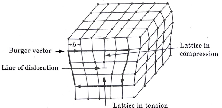
- 3. The dislocation line’s position is denoted by the symbols ⊥ and T, which indicate the participation of extra planes from the top (positive sign) and bottom (negative sign) of the crystal, respectively.
- 4. The symbol’s vertical line ⊥ points in the direction of the dislocation line in the additional partial plane.
- 5. The existence of compression and tension zones in the crystal lattice distorts the crystal near the dislocation.
- 6. The dislocation line is a region of higher energy than the rest of the crystal.
- 7. The lattice above the dislocation line is compressed, and the lattice below this line is tensioned.
b. Screw Dislocation :
- 1. The formation of a screw dislocation is shown in Fig.
- 2. The geometry of the screw dislocation influences the solidification process in an unusual way.
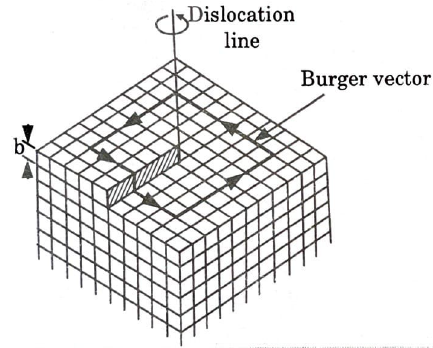
- 3. A screw dislocation has a displacement or Burger vector parallel to the linear defect, but the plane is distorted.
- 4. In this case, the atoms are displaced in two perpendicular planes, and the distortion follows a helical or screw route.
- 5. Shear forces are related with nearby atoms in this form of dislocation, and extra energy is involved along the dislocation.
- 6. Climb motion does not exist in a screw dislocation.
- 7. Three effects of a screw dislocation are of great importance :
- i. The force needed to generate and move a screw dislocation is most likely greater than the force needed to initiate an edge dislocation.
- ii. Plastic deformation is feasible under mild load without disrupting the lattice’s continuity.
- iii. Screw dislocation distorts the lattice for a long distance from the centre of the line, resulting in spiral distortion of the planes. Both sorts of dislocations (edge of screw combinations) are directly related to crystallisation and deformation.
Q2. Discuss the role of dislocations in slip.
Ans.
- 1. Dislocations are one-dimensional defects seen in actual crystalline materials that influence plastic deformation.
- 2. Because of the presence of dislocations, atomic planes can slip one atomic row at a time.
- 3. Dislocations interact with the material’s microstructure, which is responsible for its yield, work hardening, ductility, and other plastic properties.
- 4. As each dislocation moves entirely over the slip plane, it displaces the top of the crystal with regard to the section below the slip plane. The Burgers vector is commonly used to depict plane displacement.
- 5. The Burgers vector and the line are perpendicular and in the slip plane for an edge dislocation. They are parallel for the screw dislocation, and each portion of the line produces a different angle with the Burgers vector, which has a constant magnitude and direction.
Q3. Explain in brief creep test and what is its importance?
Ans. A. Creep Test Curve :
- 1. Fig. is a schematic representation of the typical constant load creep behaviour of metals.
- 2. When a load is applied, there is an instantaneous deformation that is largely elastic, as seen in the fig.
- 3. The resulting creep curve is divided into three areas, each with its own specific strain time feature.
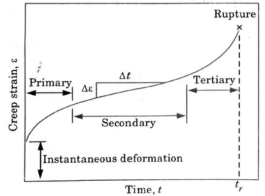
B. Different Stages of Creep Curves :
a. Primary or Transient Creep :
- 1.It is first detected by a steadily decreasing creep rate, i.e., the slope of the curve decreases over time.
- 2. The creep resistance of the material increases here.
b. Secondary Creep :
- 1. Secondary creep (stationary state creep) has a constant pace, hence the plot becomes linear.
- 2. This stage of creep is of the longest duration.
- 3. The stability of creep rate is explained as a balance between competing processes of strain hardening and recovery.
c. Tertiary Creep :
- 1. In testing creep there is an acceleration of the rate and ultimate failure.
- 2. This type of failure is known as rupture and is caused by microstructural or metallurgical changes.
- 3. In addition, with tensile loads, a neck may occur somewhere within the deformation region.
- 4. Necking lowers the test specimen’s cross-sectional area.
C. Importance of Creep Test :
- 1. It helps in finding minimum or steady state creep rate.
- 2. It helps in finding time rupture life time of components.
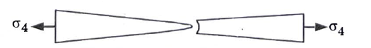
Q4. Discuss the mechanism of ductile fracture.
Ans. The mechanism involved in ductile fracture is as follows :
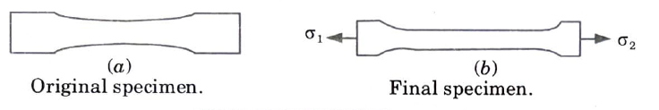
a. Neck Formation : When a load is given to the specimen, the cross-sectional area is reduced, resulting in the creation of a neck beyond the ultimate stress.
b. Crack Nucleation : Every material contains brittle and natural particles (such as cementite in steel and oxide in copper). Crack nucleates at these brittle particles due to incompatibility with the surrounding region.

c. Crack Formation and Growth : As the deformation continues, these micro voids increase, join, and merge to produce an elliptical fracture with a long axis perpendicular to the stress direction.
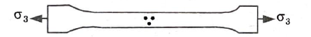
d. Crack Propagation: The crack extends perpendicular to the stress direction outward towards the surface.
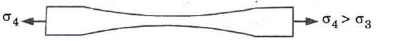
e. Cup-cone Fracture : Fracture occurs as a result of shear deformation at an angle of about 45° with the tensile axis, which causes rapid propagation of a crack across the outside perimeter of the neck. Because one of the mating surfaces is shaped like a cup and the other like a cone, this fracture is also known as a cup-cone fracture.
Q5. What is a fatigue failure ? How is a fatigue test carried out?
Ans. A. Fatigue Fracture :
- 1. Fatigue fracture is caused by the existence of fatigue cracks at surface flaws such as machine marks and slide steps, which are frequently begun by cyclic forces.
- 2. Although the initial stress concentration associated with these cracks is too low to cause brittle fracture, it may be sufficient to cause the cracks to develop slowly into the interior. Eventually, the fissures may get deep enough that the stress concentration surpasses the fracture strength, resulting in unexpected failure.
- 3. The brittleness of the material under test determines the amount of the crack propagation process.
- 4.In brittle materials, the crack expands to a critical size and quickly propagates through the structure, but in ductile materials, the crack grows until the remaining region cannot take the load and a virtually ductile fracture occurs.
- 5. The look of fracture can be used to identify fatigue failures.
B. Fatigue Tests :
- 1. Fatigue tests are conducted in the laboratory to measure a material’s ability to endure repeated applied stresses.
- 2. Fatigue testing is necessary to determine the varied fatigue properties of materials based on the type of load and how it is applied.
- 3. Simple axial loading, bending, torsion, and a combination of these three are the most common types of loading.
- 4. Fig. shows a constant load machine used for fatigue testing.
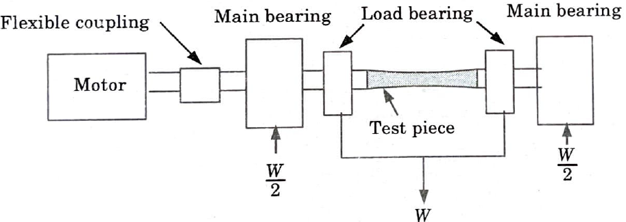
- 5. The machine is loaded with a test specimen in the shape of a cantilever that extends from a shaft. An electric motor powers the shaft.
- 6. Ball bearings are used to apply a dead load to the machine. The bearing relieves the motor of the significant bending moment delivered to the specimen.
- 7. During rotation, any given place on the specimen’s surface alternates between a condition of maximum tensile stress and a state of highest compressive stress.
- 8. As the specimen spins, the stress varies sinusoidally.
- 9.The surface has the highest stress and the centre has the lowest.
- 10. The number of cycles will be determined by the applied stress value, and exhaustion may result. Where the value of the stress is large, the number of cycles will be reduced.
- 11. If, on the other hand, the applied stress is lower, the number of cycles must be increased. Finally, a stress is attained below which failure will not occur within the parameters of the usual test. This level of stress is referred to as the endurance limit.
- 12. If fracture does not occur within the material’s stated cycles, it is considered that fracture will not occur.
Q6. What are the different ways of improving fatigue life?
Ans. Different ways of improving fatigue life are as follows :
- 1. Sharp corners, for example, are avoided, causing stress concentrations to disappear or significantly decrease.
- 2. Materials with finer grain sizes should be utilized.
- 3. Polishing the surfaces should be used to remove surface imperfections and fissures.
- 4. Surface procedures such as shot peening, shot or sand blasting, and so on introduce compressive pressures.
- 5. To develop robust surface layers, nitriding and carburizing processes should be carried out.

Material Science Important Links:
| Label | Link |
|---|---|
| Subject Syllabus | Syllabus |
| Short Questions | Short Question |
| Important Unit-1 | Unit-1 |
| Important Unit-2 | Unit-2 |
| Important Unit-3 | Unit-3 |
| Important Unit-4 | Unit-4 |
| Important Unit-5 | Unit-5 |
| Question paper – 2021-22 | 2021-22 |
AKTU Important Links | Btech Syllabus
| Link Name | Links |
|---|---|
| Btech AKTU Circulars | Links |
| Btech AKTU Syllabus | Links |
| Btech AKTU Student Dashboard | Student Dashboard |
| AKTU RESULT (One VIew) | Student Result |
Important Links-Btech (AKTU) | Material Science Syllabus
| Label | Links |
|---|---|
| Btech Information | Info Link |
| Btech CSE | CSE-LINK |
| Quantum-Page | Link |
| Material Science Syllabus | Syllabus-material Science |
3 thoughts on “Unit 3 Mechanical Properties in Material Science – Important Question Series”