
Providing B.Tech. (Sem. 3rd) Odd Semester Theory Examination, 2021-22 Material Science Question Paper with Solution. An important part of the course for the AKTU B.Tech program is the Material Science exam, which measures students’ understanding of the core ideas behind materials engineering. You must follow to this article in to successfully complete this exam.
Hi there 🙏, make sure to keep this in mind also if you're seeking for additional useful information on this topic

Important Questions For Material Science :
*Unit-01     *Unit-02
*Unit-03    *Unit-04
*Unit-05    *Short-Q/Ans
*Question-Paper with solution 21-22
Section A: Short Question in Material Science (AKTU)
a. Define solid solution strengthening.
Ans. Solid solution strengthening is a type of alloying that can be used to increase the strength of a pure metal. The procedure involves inserting atoms of one element into the crystalline lattice of another, producing a solid solution.
b. Explain concept of magnetism.
Ans. Magnetism is the phenomena in which one material exerts an attractive or repulsive force on another.
c. Write down % composition of carbon in steel and cast iron.
Ans. Steel can have up to 1% carbon, whereas cast iron can include up to 2-4% carbon.
d. What is the purpose of tempering?
Ans. Purpose of temperature are as follows:
- 1. It makes hardened steel less brittle.
- 2. It increases ductility.
- 3. It relieves internal stresses.
- 4. It increases the toughness of steel.
e. Explain the properties of stainless steel with application.
Ans. Properties of Stainless Steel:
1. It is hardenable.
2. It is pliable, ductile, and corrosion resistant.
Application of Stainless Steel: Valves, Pumps, surgical instrumental, razors, blades, turbine blades, etc.
f. What do you mean by superconductivity?
Ans. Superconductivity: It is a feature of superconductors that exhibits exceptional magnetic and electrical behaviour at extremely low temperatures (near to absolute zero).
g.Differentiate annealing vs normalizing.
Ans.
| S.No. | Annealing | Normalizing |
| 1. | It requires low heating range. | It requires high heating range. |
| 2. | Mechanical properties obtained are better. | Mechanical properties obtained are not as good as in annealing. |
h. Define creep with example.
Ans. Creep is the time-dependent permanent distortion that happens when most materials are stressed.
i. Explain matrix and reinforcement of composites materials.
Ans. A. Role of Matrix in Composites: Matrix in composition is used:
1. To bind the fibers together in such a way that the applied stress is distributed evenly across the fibers.
2. To keep the fibers’ surface from being harmed.
3. To separate the fibers and inhibit crack propagation.
B. Role of Reinforcement in Composites: Reinforcement in composites is used:
1. To carry weight along the length of the fibre in one direction to generate strength and stiffness.
2. To give customised qualities in the direction of the loads applied to the finished product.
j. What are the objectives of heat treatment?
Ans. Objectives of heat treatment are as follows:
1. Produces the surface as well as the tough internal sections.
2. Modify magnetic and electrical properties.
3. Improve machinability.
4. Refine the grains.
Section B: Long Questions For Material Science (AKTU)
a. State and explain the Hume-Rothery rule for the formation of a solid solution.
Ans. 1. Hume-Rothery provided some alloy development criteria for substitutional solid solution. These are known as Hume-Rothery Rules and are described below:
a. Chemical Affinity Factor:
1. The more two metals’ chemical affinity, the more restricted their solid solubility.
2. When two metals have a high chemical affinity, they tend to form an intermediate phase rather than a solid solution.
b. Relative Valence Factor:
1. If the alloying element has a different valence than the base metal, alloying will modify the number of valence electrons per atom, known as the electron ratio.
2. Crystal structures are more sensitive to electron ratio decreases than increases. As a result, a high valence metal can only dissolve a little amount of a lower valence metal, whereas the lower valence metal may have good solubility for a higher valence metal.
c. Relative Size Factor :
1. When the size difference between two metallic atoms is less than 15%, the metals are considered to have a favourable size factor for solid solution formation.
2. Solid solution formation is severely limited when the size factor exceeds 15%, and is usually only a fraction of one percent.
d. Lattice Type Factor:
1. Only metals with the same lattice type can produce a full series of solid solutions.
b. Explain in brief creep test and what is its importance?
Ans.
A. Creep Test Curve:
- 1. Figure depicts a schematic illustration of metal constant load creep behaviour.
- 2. When a load is applied, there is an instantaneous deformation that is largely elastic, as seen in the figure.
- 3. The resulting creep curve is divided into three areas, each with its own specific strain time feature.

B. Different Stages of Creep Curves:
a. Primary or Transient Creep:
- 1. It is first detected by a steadily decreasing creep rate, i.e., the slope of the curve decreases over time.
- 2. Here the material experiences an increase in creep resistance.
b. Secondary Creep:
- 1. Secondary creep (stationary state creep) has a constant pace, hence the plot becomes linear.
- 2. This stage of creep is of the longest duration.
- 3. The stability of creep rate is explained as a balance between competing processes of strain hardening and recovery.
c. Tertiary Creep :
- 1. There is an acceleration of the rate and eventual failure in testing creep.
- 2. This type of failure is known as rupture and is caused by microstructural or metallurgical changes.
- 3. In addition, with tensile loads, a neck may occur somewhere within the deformation region.
- 4. Necking lowers the test specimen’s cross-sectional area.
C. Importance of Creep Test:
- 1. It helps in determining the minimal or steady-state creep rate.
- 2. It helps in determining the time rupture life time of components.
c. What are dielectric materials? Explain the application of dielectrics.
Ans. A. Dielectric Materials:
- 1. A dielectric substance is one that is electrically insulating (nonmetallic) and has or can be manufactured to have an electric dipole structure, which means that positive and negative electrically charged entities are separated on a molecular or atomic level.
- 2. Insulators are solids with an energy gap of 3eV or greater.
- 3. It is nearly impossible to excite electrons from the valance band to the conduction band in such materials using an applied field or typical thermal energy.
- 4. Insulators, often known as dielectrics, are hence very poor heat and electrical conductors.
B. Application of Dielectrics: Application of dielectric material are as follows:
- 1. They are mostly utilised as the charge storage material between the metallic plates in capacitors. This also keeps the plates from coming into direct contact with one another.
- 2. Used in dielectric resonator antennas for creating and receiving microwave signals.
- 3. In transformers, they are used as cooling materials.
- 4. Used to cover wires and conducting materials as an insulator.
- 5. Used in piezoelectric and electro-optic devices as well.
d. Draw and explain TTT diagram from eutectoid steel. Explain important transformation taking place in it on cooling.
Ans. A. TTT-Diagram:
- 1. The Temperature-Time-Transformation diagram depicts the relationship between the beginning and end of the production of various microstructures.
- 2. Because its shape is identical to the letter ‘C’ in the English alphabet, it is known as a C-curve.
- 3. The nose of this curve represents the shortest time required for a specific change.
- 4. The critical cooling curve is the line that passes through the nose (or the tangent at the nose of the C-curve) and its slope is the crucial cooling rate.
- 5. The transition of austenite to pearlite is depicted in Fig. The leftmost C-curve depicts the beginning of austenite transition into pearlite.
- 6. This curve has 0% pearlite and 100% austenite. The dashed curve represents 50% austenite transformation into pearlite, and the rightmost C-curve shows (complete curve) 100% pearlite transformation.
- 7. These curves are only accurate for transformations in which the alloy temperature is kept constant during the reaction.
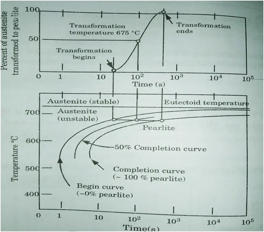
- 8. Thus these plots are also known as isothermal transformation diagrams or TTT diagrams.
- 9. Depending on the cooling rate, various microstructures such as pearlite (coarse or fine), bainite, austenite + martensite, and martensite can be formed.
- 10. Line pearlite is produced via annealing when the cooling rate is slow.
- 11. The cooling rate is high during normalisation, resulting in the bainite structure.
- 12. Fig. shows a complete TTT diagram showing its various phases.

B. Importance of TTT Diagram:
- 1. It depicts the structure acquired at various cooling rates.
- 2. It depicts the cooling rate required to convert austenite to pearlite, bainite, or martensite graphically.
- 3. It depicts the amount of time required for transformation to various phases.
e. Draw stress–strain curve for any metal. Elaborate all points associated with explanation.
Ans. Fig. depicts a stress-strain diagram for a mild steel specimen.The following salient points are observed on stress-strain curve:

i. Limit of Proportionality (A): It is the stress limiting value over which stress is proportional to strain.
ii. Elastic Limit: This is the maximum stress value at which the strain vanishes completely and the original length is recovered if the material is stretched and then released (unloaded). This location is barely above the proportionality limit.
iii. Upper Yield Point (B): This is the stress at which the load begins to decrease and the extension begins to increase. This is referred to as material yielding.
iv. Lower Yield Point (C): The stress remains constant at this point, but the strain increases for a short period of time.
v. Ultimate Stress (E): This is the maximum stress that the material can withstand. At this point, the cross-sectional area of a given section begins to shrink rapidly. This is known as neck formation.
vi. Breaking Point (F): The stress at which the specimen eventually fails is referred to as the breaking point. At this moment, the strain is between 20% and 25%.
Section – C
a. Draw neat iron carbon equilibrium diagram with explanation of each phase, compositions, and temperature. Explain the microstructure of pearlite and eutecoid steels.
Ans. A. Iron-Carbon Equilibrium Diagram:
- 1. The Fe-C phase diagram is presented in Fig. Carbon is an iron interstitial contaminant that is soluble in iron.
- 2. There are different types of solid phases of iron-carbon solid solution as:
- a. At room temperature, ferrite (𝛼-iron) is stable and it has a BCC crystal structure.
- b. At temperature 912
C, Ferrite transforms to austenite (γ-iron).
- c. Above the temperature 1394
C, austenite transform to a BCC crystal structure δ-phase. δ-phase has a melting point of 1538
C.
- 3. Cementite (Fe3C) forms when solubility limit of carbon in 𝛼-ferrite is exceeded below 727
C.
- 4. Fe3C also co-exists with the
-phase in the region 727
C to 1147
C.
- 5. Cementite is a particularly hard and brittle material. Cementite is a metastable compound rather than an equilibrium molecule.
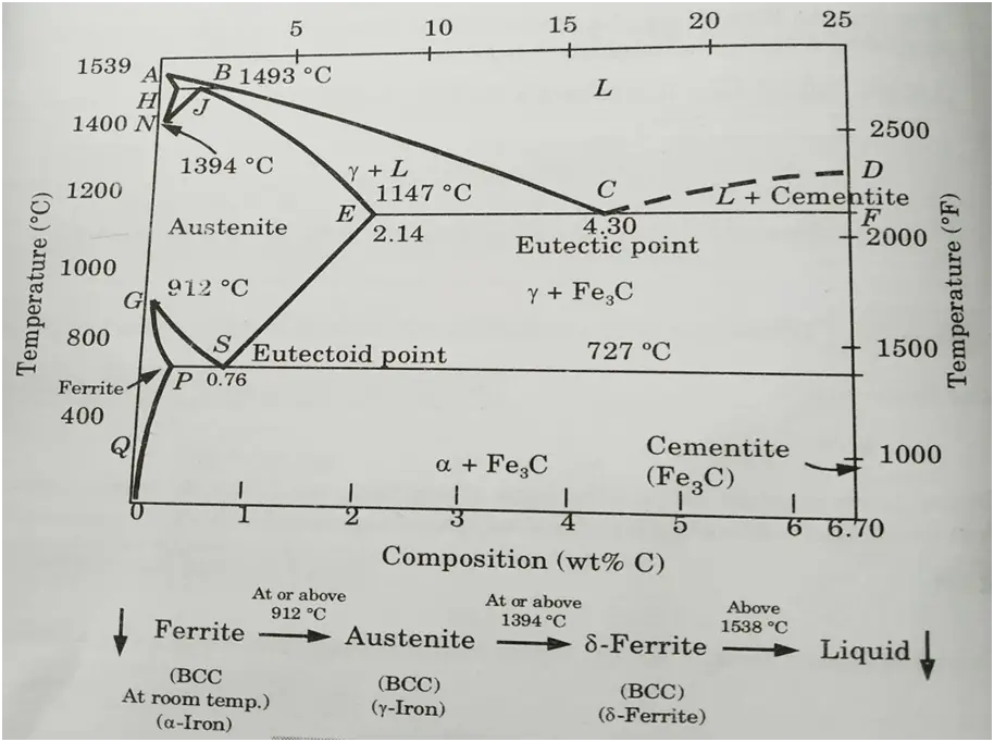
- 6. Executive point of Fe3-C equilibrium diagram are explained as following :
i. Eutectic Point:
- 1. Point C on the phase diagram represents the eutectic point.
- 2. Eutectic composition = 4.3% carbon at point C (percent by weight) 1147 °C is the eutcetic temperature.
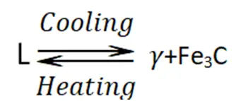
- 3. There is a state of equilibrium between the liquid state (L) and two solid phases (γ phase and cementite).
ii. Eutectoid Point:
- 1.Point S is indicated as eutectoid point.
- 2. At point S, there is an equilibrium state between solid state and two solid phases (
and cementite).
- 3. Eutectoid composition = 0.76% carbon (percent by weight)

B. Microstructure of Pearlite and Eutectoid Steels:
- 1. If a 0.8% Ceutectoid steel sample is heated to around 750 °C and maintained for a long enough time, its structure will become homogeneous austenite. This is known as austenitizing.
- 2. The structure of this eutectoid steel will stay austenitic if it is gently cooled to just over the eutectoid temperature.
- 3. Further cooling to the eutectoid temperature or slightly below will cause the entire structure to transition from austenite to a lamellar structure of ferrite and cemenite Fe, C.
- 4. Just below the eutectoid temperature at point b in Fig., the lamellar structure will appear.
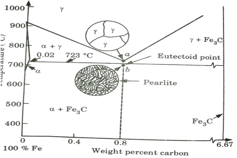
- 5. Because it resembles mother of pearl, this eutectoid structure is known as pearlite.
- 6. Because the carbon solubility in ferrite and Fe3C changes very little from 727 °C to room temperature, the pearlite structure will remain fundamentally constant in this temperature range.
b. Differentiate between Rockwell, Brinell and Vickers hardness testing.
Ans.
| S. No. | Rockwell | Brinell | Vickers |
| 1. | No specimen preparation required. | The specimen surface can be rough. | Specimens need to be prepared. |
| 2. | Hardness value directly readable, no optical evaluation required. | Good illumination of the test indent is important for ensuring correct evaluation of the test indent. | Due to the need to conduct optical indent evaluation, Vickers hardness testers must be equipped with an optical system. |
| 3. | Quick and cost-effective process. | The process is slow. | The process is rather slow. The test cycle takes somewhere between 30 and 60 seconds. |
| 4. | Non- destructive testing. | Limitations is applying the method on thin specimens of very hard materials. | Non-destructive testing is possible. |
| 5. | Does not reduce service life of component. | Reduces service life of component. | Does not reduce service life of component. |
| 6. | All types of material are tested by this method. | Limited materials are tested by method. | Limited materials are tested by method. |
| 7. | Contact angle changes While using the ball indenter. | Contact angle changes according to materials. | Contact angle remains same. |
4a. Explain:
i. Ferromagnetism
Ans. 1. Certain materials have a constant atomic dipole moment.
2. They are placed in a strong magnetic field and strongly magnetised in the direction of the applied field; such materials are known as ferromagnetic materials. As an example, consider the iron, nickel, and cobalt alloy.
3. Despite the randomising nature of their atom’s thermal agitation, they have a tendency to align themselves in the direction of the field.
4. These material features are known as ferromagnetism.
ii. Diamagnetism
Ans. It is the phenomenon of a material’s weak, negative, repulsive reaction to an applied magnetic field. Diamagnetic materials have a low magnetic susceptibility.
iii. Shape memory alloys.
Ans. 1. A shape memory alloy is an alloy that can be distorted when cold but returns to its pre-deformed shape when heated.
2. Memory metal, memory alloy, smart metal, smart alloy, and muscle wire are some other names for it.
3. Shape memory alloy components can be lightweight, solid-state replacements to traditional actuators such as hydraulic, pneumatic, and motor-based systems. They are also useful for making hermetic couplings in metal tube.
4b. What is solid solution? Enlist types of solid solution and explain it.
Ans. A. Solid Solution:
- 1. A solid solution is a solution of one or more solutes in a solvent in a solid state.
- 2. When the crystal structure of the solvent stays unaffected by the addition of the solutes, and the mixture remains in a single homogenous phase, such a mixture is called a solution rather than a compound.
- 3. Solid solutions form easily when the solvent and solute atoms have comparable sizes and electron structures, resulting in a chemically homogenous solution in which the constituent atoms of the elements cannot be distinguished physically or mechanically separated.
- 4. A single phase or solid solution is formed by the homogenous distribution of two or more elements in the solid state.
B. Types of Solid Solution: These are the following two types:
a. Substitutional Solid Solution:
- 1. A solute atom can take one of two positions in the solvent (matrix) metal lattice.
- 2. If the two atoms are similar in size, the solute atom will randomly substitute for one of the matrix atoms in the crystal lattice. A substitutional solid solution is the name given to this type of structure.
- 3. Brass, for example, is an alloy of copper and zinc that readily forms solid solution because the atoms of these elements have similar sizes and electron structures.
- 4. Substitutional solid solutions are of two types:
- i. Random substitutional solid solutions, and
- ii. Ordered substitutional solid solution.
b. Interstitial Solid Solution:
- 1. To generate an interstitial solid solution, a few relatively tiny atoms can be accommodated in the interstices between solvent atoms.
- 2. Carbon in iron is an example of such a solution, which serves as the foundation for steel hardening.
- 3. Interstitial solid solutions often have relatively limited solubility and are regarded as secondary in importance.
- 4. Some alloys form significant amounts of both interstitial and substitutional solid solutions.
5a. Define composites. Write down the types of composites and explain them briefly.
Ans. A. Composite Materials:
1. Composite materials are multiphase materials that are created intentionally to have the properties of both materials utilised to construct a composite material.
2. Composites are made up of a metal alloy, ceramics, and polymers.
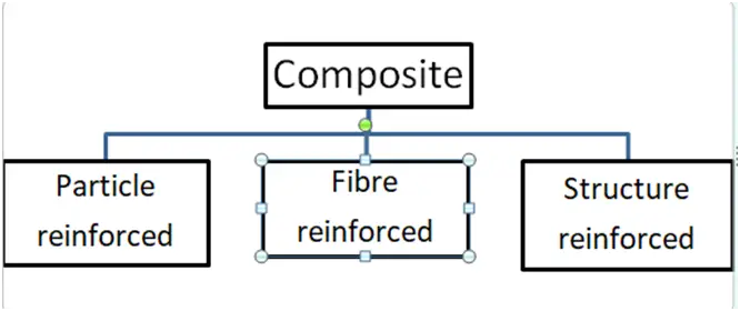
B. Classification of Composite Material:
a. Particle Reinforced Composites:
1. Particle reinforcing is a technique used to strengthen composite materials.
2. Particle reinforced composites gain stiffness while also increasing strength and toughness.
3. This type of composite is the most commonly utilised since it is widely available and inexpensive.
4. Particle reinforced composites are used in applications requiring high levels of wear resistance, such as road surfaces.
5. They are of two kinds :
i. Dispersion Strengthened Composites :
1. Particles in dispersion strengthened composites are considerably smaller, measuring 0.01 -0.1 um in size.
2. Here the strengthening occurs at atomic/molecular level.
3. The strength of dispersion enhanced composites is maintained over long periods of time at high temperatures.
4. For example, nickel alloy with 3% Tho (by volume), sintered aluminium powder, and so on.
ii. Large Particle Composites :
1. The dispersed phase in large particle composites is tougher and stiffer than the matrix.
2. Large particle composites are used with all three types of materials (metals, polymers and ceramics).
3. Example: Concrete, cements, tungsten carbide etc.
b. Fibre Reinforced Composites:
1. A fibre reinforced composite (FRC) is a composite building material that consists of three components:
i. The fibres as the discontinuous or dispersed phase,
ii. The matrix as the continuous phase, and
iii. The fine interphase region also known as the interface.
2. FRC is created by cross-linking cellulosic fibre molecules with resins in a material matrix, resulting in a product with excellent structural qualities.
3. FRC can be recycled up to 20 times, allowing scrap FRC to be reused again and again.
4. There are two types of fiber reinforced composites present:
i. Continuous or aligned fibre composites, and
ii. Discontinuous fibre composites.
c. Structural Composites :
1. Typically, a structural composite is made up of both homogeneous and composite components.
2. Its qualities are determined not only by the constituent material properties, but also by their geometrical design.
3. On the basis of their geometry it can be classified as :
i. Laminar Composites:
1. Layers of two-dimensional sheets or panels are layered and cemented together in laminar composites.
2. Because of this shape, a varied strength occurs within the composite. This strength will vary from layer to layer.
ii. Sandwich Panels :
1. A sandwich panel is made up of two outer sheets that are separated by and adhered to a thicker core.
2. These are used to create weight beams with high stiffness and strength.
3. The outside sheets are often stiffer and stronger, whereas the core material is light in weight and has a low modulus of elasticity.
5b. What is diffusion? Illustrate the Fick’s laws of diffusion.
Ans. Diffusion:
1. Diffusion refers to the movement of atoms or solid.
2. Diffusion is the movement of atoms and molecules to new locations within a material as a result of heat agitation, resulting in a more homogeneous composition.
Fick’s first law:
1. Fick’s first law describe the rate at which diffusion occurs. This states that
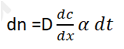
Where, dn = Amount of metal in kg that crosses a plane normal to the direction of diffusion,
dc/dx = Slope of concentration gradient,
D = Diffusion coefficient,
= Area of plane across which diffusion takes place, and
dt = Duration of diffusion.
2. On rearranging, the equation become,
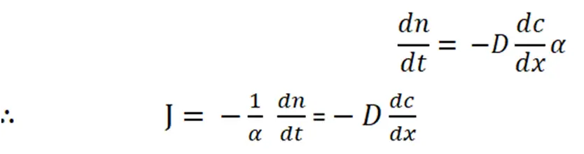
Where, J = The flux or the number of atoms moving from unit area of one plane to unit area of another per unit time. It is proportional to the concentration gradient.
The negative sign indicates that flow occurs down the concentration gradient.
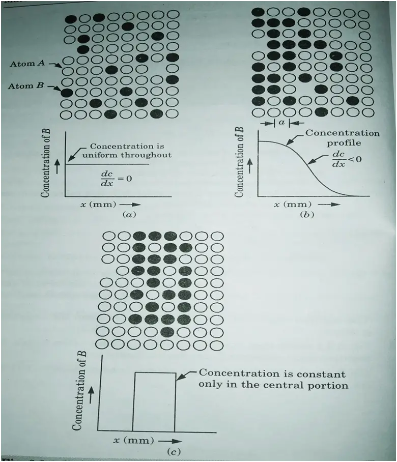
3. Fig. shows that the concentration gradient varies with x. A large negative slope corresponds to high diffusion rate.
4. The B atoms will diffuse from the left side in accordance with Fick’s first law.
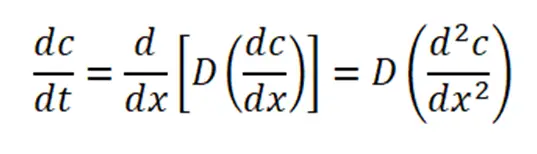
Fick’s Second Law:
1. Fick’s second law is an extension of the first law to nonsteady state flow.
2. Fick’s first law calculates the instantaneous mass flow rate (flux) past any plane in a solid but provides no information about the concentration’s temporal dependency.
3. Fick’s second law contains the time dependency, which can be determined using Fick’s first law and the law of conservation of mass.
4. According to Fick’s second law,
5. Fig. is a schematic illustration of the time dependence of diffusion.
6. The curve labeled t1 corresponds to the concentration profile at a given instant of time.

7. At a later time t2, the concentration profile has changed. This change is due to the diffusion of B atoms that has occurred in the time interval t2 – t1.
8. The t2 curve represents the concentration profile at as still later times.
9. The diffusion process is trying to distribute B atoms uniformly throughout the solid solution.
10. Fig. also indicates that as time passes, the concentration gradient becomes less negative. This means that as the diffusion process develops, the diffusion rate slows.
6a. What is polarization? Discuss the frequency effects on polarization.
Ans. A. Polarization:
- 1. The alignment of permanent or induced atomic or molecule dipole moments with an externally applied electric field is referred to as Polarization.
- 2. There are three types of polarization sources: electronic, ionic, and orientation.
Frequency Effects on Polarization:
- 1. The effect of frequency on polarization is shown in Fig.

- 2. At high frequencies (> 1014 Hz), the concentration is purely due to electronic polarization, suggesting that only free electrons, such as those found in metals, can respond to an electric field. Because of this, metals are excellent optical reflectors.
- 3. When the frequency increases, dipolar polarization cannot follow the electric field in the microwave zone at 1010 Hz.
- 4. Ionic polarization loses its response to an electric field in the infrared or far-infrared range at 1013 Hz.
- 5. Around 1015 Hz, electronic polarization loses its responsiveness in the UV range.
6b. Draw he hysteresis curve and explain it in detail.
Ans.
- 1. Magnetic induction lags behind the magnetizing field when a ferromagnetic material is placed in one. This is referred to as hysteresis.
- 2. When a ferromagnetic material, such as iron, is gradually magnetized by gradually increasing the intensity of the magnetic field H, magnetic induction begins to increase.
- 3. Fig. shows a graph plot of B-H. When the magnetic field is increased from O to G, the fraction ‘Oa’ corresponds to initial magnetization.
- 4. The variation in magnetic induction is provided by the curve abcdefa when the value of the magnetizing field is adjusted from G to -G and -G to G. This closed curve is referred to as a hysteresis curve or a hysteresis loop.

- 5. At point b, where H = 0, B ≠ 0 but B → B, known as residual induction or retentivity of the magnetic field applied in the negative direction.
- 6. At point c, B= 0, H ≠ 0 but H → Hc known as coercive force or coercivity.
7a. What are nanomaterials? State the potential application of nanomaterials.
Ans. A. Nanomaterials:
- 1. Nanomaterials are materials that have any external dimension in the nanoscale or that have an internal or surface structure in the nanoscale (length range approximately from 1 nm to 100 nm).
- 2. This includes nanoobjects, which are discrete pieces of material, as well as nanostructured materials, which have internal or surface structure on the nanoscale; a nanomaterial can fall into both of these categories.
- 3. Nanomaterials that occur naturally (e.g., volcanic ash, soot from forest fires) or are produced as byproducts of combustion processes (e.g., welding, diesel engines) are typically physically and chemically diverse and are commonly referred to as ultrafine particles.
- 4. Engineered nanomaterials, on the other hand, are created and built with precise physicochemical qualities for a certain purpose or function.
B. Applications of Nanomaterials:
i. Microelectronics : In microelectronics, smaller electronic components result in faster switching times. Nanotechnology encompasses the creation of nanowires for application in semiconductors.
ii. Machine Tools: Some nanocrystalline materials, such as tungsten carbide and titanium carbide, are tougher than conventional materials and have higher wear and erosion resistance, making them suitable for use in cutting tools and drill bits.
iii. Motor Vehicles and Air Craft: The thermal energy generated by engines is largely lost. This can be mitigated by covering the cylinders with nanocrystalline ceramics like zirconia and alumina. The combustion of the fuel is completed by retaining extra heat energy.
iv. Aerogels: Aerogels are nanocrystalline substances. Because they are porous, air is trapped at the interstices. Using these materials for insulation in businesses and residences reduces cooling and heating expenditures significantly by conserving energy.
v. Textiles Field: Clothes composed of nanofibers are wrinkle-free and water-resistant. At low temperatures, they can be washed less frequently.
vi. Computer: Quantum computers use fast quantum algorithms and have quantum bit memory space (qubit), allowing them to do several computations at once.
vii. Cosmetics : Sunscreens made from mineral nanoparticles, such as titanium dioxide, provide a number of advantages. In comparison to the bulk material, they have superior UV protection.
7b. Explain the types, properties and applications of carbon nanotubes.
Ans. A. Types of Carbon Nanotubes:
i. Single Walled Carbon Nanotubes:
- 1. These are of three different types. They are:
- i. Arm chair,
- ii. Zig-zag, and
- iii. Chiral type structures.
- 2. The majority of single-walled carbon nanotubes (SWCNT) have a diameter close to 1 nanometre and a tube length that can be thousands of times longer.
- 3. A SWCNT’s structure can be visualised as a seamless cylinder wrapped in a one-atom thick sheet of graphite called graphene.
- 4. The chiral vector is a pair of indices (n, m) that represents how the graphene sheet is wrapped.
- 5. The integers n and m represent the number of unit vectors along two directions in graphene’s honeycomb crystal lattice. When m = 0, the nanotubes are referred to as zig-zag. If n = m, the nanotubes are referred to as arm chairs. Otherwise, they are referred to as chiral.
- 6. The first nanotube in Figure (a) is an example of an arm chair nanotube, while the second nanotube in Figure (b) is an example of a zig-zag nanotube. Both of these nanotubes are quite symmetric. The pattern of hexagons around the circle is referred to by the titles arm chair and zig-zag.
- 7. The third and most common type of tube is chiral, which means that it can exist in two mirror-related forms. Fig. (c) shows an example of a chiral nanotube .
- 8. Single walled carbon nanotubes are the most important type of carbon nanotube because they have crucial electric properties that multi walled carbon nanotube (MWCNT) variations do not.
- 9. Single-walled carbon nanotubes are the most promising prospects for miniaturising electronics beyond the micro electromechanical scale that now serves as the foundation of modern electronics.
- 10. Electric wire is the most fundamental building block of these systems, and SWCNTs can be good conductors.

ii. Multi Walled Carbon Nanotubes:
- 1. MWCNTs (multi walled carbon nanotubes) are a type of carbon nanotube in which many single walled carbon nanotubes are nestled together.
- 2. These are hollow, cylindrically formed carbon allotropes with a high aspect ratio (length to diameter ratio).
- 3. Their performance and applicability are determined not only by their aspect ratio, but also by the degree of entanglement and straightness of the tubes, which is determined by both the degree and dimension of flaws in the tubes.
- 4. MWCNTs have a high tensile strength and, when combined with a thermoplastic or thermoset material, can greatly boost its strength.
- 5. When appropriately integrated into a composite framework, MWCNTs are very conductive.
- 6. They have excellent chemical stability. However, nanotubes can be functionalized to improve composite strength and dispersibility.
- 7. MWCNTs have a thermal stability above 600 °C.
B. Properties and Application of Carbon Nanotubes:
Properties of Carbon Nanotubes :
- 1. Carbon nanotubes are extremely pliable. They are more resistant to strain than steel.
- 2. They have electrical properties that range from semiconductors to excellent conductors.
- 3. Carbon nanotubes are excellent thermal conductors. Their heat conductivity is more than double that of diamond.
- 4. The strength-to-weight ratio of carbon nanotubes is extremely high. They have low density.
- 5. Carbon nanotubes are more chemically inert than other forms of carbon.
Applications of Carbons Nanotubes :
a. Electronics :
- 1. The carbon nanotube with a single wall can function as a transistor. As logic structures, pairs of nanotubes or crossed nanotubes are visible.
- 2. When a line of hexagons forms a helix, the tube becomes a semiconductor. A rectifying diode is formed by a single nanotube with a natural junction.
- 3. A nanotube works in flat panel displays because of its field emission property. Batteries contain nanotubes.
b. Hydrogen Storage: Nanotubes can store hydrogen, helium, oxides, and metals such as copper.
c. Mechanical Machines: In nanomachines, nanotubes can serve as axles. Building gear teeth on nanotubes is preferred for translating various rotational motions.
d. Space Elevators:
- 1. Long nanotube filaments are utilised in fibre reinforced polymers because they are lighter. As a result, they are utilised in aircraft, space ships, and land vehicles.
- 2. Carbon nanotubes, like graphite, can tolerate high temperatures and are thus employed to shield spacecraft during re-entry into the atmosphere.
- 3. Carbon nanotubes have a high Young’s modulus, which makes them resistant to aeronautical strains.
E. Hospitals :
1. Carbon nanotubes are so tiny that they can pass through the skin without causing pain. 2. Blood can be collected from diabetes patients using nanostraws to determine glucose levels and deliver insulin as needed.

Material Science Important Links:
| Label | Link |
|---|---|
| Subject Syllabus | Syllabus |
| Short Questions | Short Question |
| Important Unit-1 | Unit-1 |
| Important Unit-2 | Unit-2 |
| Important Unit-3 | Unit-3 |
| Important Unit-4 | Unit-4 |
| Important Unit-5 | Unit-5 |
| Question paper – 2021-22 | 2021-22 |
AKTU Important Links | Btech Syllabus
| Link Name | Links |
|---|---|
| Btech AKTU Circulars | Links |
| Btech AKTU Syllabus | Links |
| Btech AKTU Student Dashboard | Student Dashboard |
| AKTU RESULT (One VIew) | Student Result |
Important Links-Btech (AKTU) | Material Science Syllabus
| Label | Links |
|---|---|
| Btech Information | Info Link |
| Btech CSE | CSE-LINK |
| Quantum-Page | Link |
| Material Science Syllabus | Syllabus-material Science |
1 thought on “Material Science Latest Question Paper 2021-22 – AKTU Btech”