
Improve your power system protection knowledge with our amazing collection of exam-style questions and complete solutions from previous year.
Dudes 🤔.. You want more useful details regarding this subject. Please keep in mind this as well.

Important Questions For Power System Protection:
*Quantum          *B.tech-Syllabus
*Circulars           *B.tech AKTU RESULT
* Btech 4th Year
Section A: Short Question In Power System Protection
a. Need for protective systems.
Ans.
- 1. It is needed for the protection of short circuit condition arising in a power system.
- 2. To minimize damage to the system components involved in the failure.
b. Essential qualities of protection.
Ans.
- 1. Reliability
- 2. Speed and time
- 3. Sensitivity
- 4. Stability
- 5. Adequateness.
c. What are the different types of induction relay ?
Ans. Induction type relay: Induction relays are of two types:
- i. Induction disc type
- ii. Induction cup type.
d. What do you understand by the term “Current Chopping”?
Ans.
- 1. There are times when it is important to interrupt tiny inductive currents, such as when removing transformers with no load. A transformer’s no load current is nearly negligible power factor lagging.
- 2. This current is typically less than the breaker’s regular current rating. Interrupting such a current places a heavy load on the circuit breaker. This is referred to as current chopping.
e. What do you mean by reverse power protection?
Ans. It is the most common type of generator/alternator protection. When the turbine fails to provide mechanical power, it is utilised to safeguard the alternator/generator from driving action.
f. What do you understand by pilot wire protection scheme ?
Ans.
- 1. In normal operation, the two currents at both ends are equal, and pilot wires carry no current, keeping relays inactive.
- 2. When there is a defect, the two currents at the two ends are no longer the same, causing circulating current to flow via the pilot wires. This causes relays to trip, causing circuit breakers to trip and isolating the damaged area.
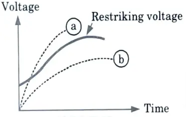
g. What is re-striking voltage transient ?
Ans. Restriking voltage: Restriking voltage is the transient voltage that emerges across the circuit breaker contacts at the instant of arc extinction.
h. Explain basic concept of DC circuit breaker.
Ans. The requirement of DC circuit breaking is to interrupt load currents in circuits with high potential with respect to ground because the short circuit current can be regulated to normal load currents utilising grid control.
i. Differentiate between static and dynamic overcurrent relay.
Ans.
| S. No. | Points | Static overcurrent relay | Dynamic overcurrent relay |
| 1. | Power consumption | Very less1 milliwatt | High 2 watt |
| 2. | Moving contacts | No moving contacts. | Moving contacts are present. |
| 3. | Size | Compact (small) | Large |
| 4. | Accuracy and speed | High | Less |
j. Explain how the phase comparator is different from amplitude comparator.
Ans. A phase comparator compares two input quantities in phase angle, regardless of magnitude, and activates when the phase angle between them is < 90, whereas an amplitude comparator compares the magnitudes of two input numbers, regardless of angle.
Section B : Long Questions of Power System Protection
a. Explain what you understand by pick up and reset value of the actuating quantity.
Ans.
- A. Pick up value: It is the value of actuating quantity at which the relay is on the verge of operation. These quantities can be current, voltage, frequency etc.
- B. Reset value :
- 1. A relay is s¡ id to dropout or reset when it moves from the ON position to the OFF position.
- 2. The value of the characteristic quantity below which this change occurs is known as dropout or reset value.
b. Describe the various types and working principle of differential relays.
Ans. Differential relay: Differential relay is a suitably connected overcurrent relay which operates in a condition when the phasor difference of currents at the two ends of a protected element exceeds a particular value. Various types of differential relays are :
- A. Simple differential relay :
- 1. As I1 = I2 = IL and I1s = I2s = IL so I1s – I2s = 0
- 2. Simple differential relay is an overcurrent relay having operating coil which carries the phasor difference of currents at the two ends of a protected element.
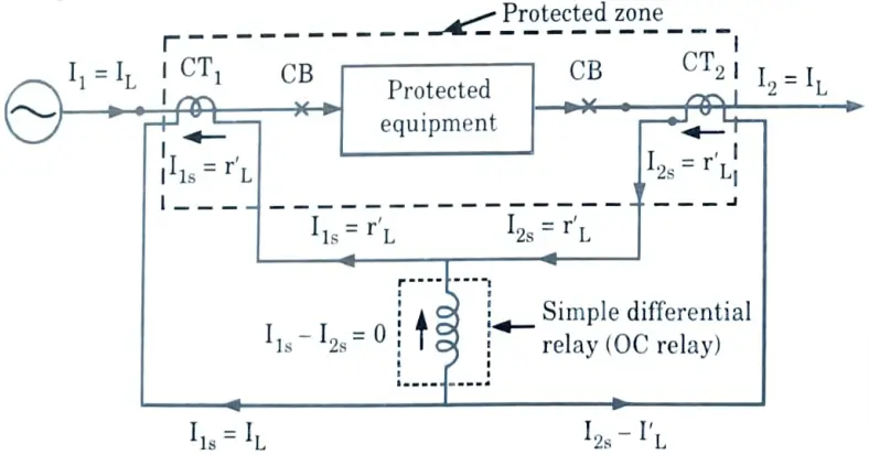
- 3. It activates when the phasor difference of the CTs’ secondary current surpasses a predefined value.
- 4. The pilot wire circuit connects the secondary of the CTs at the two ends of the protected element.
- 5. The difficulty with simple relays occurs during heavy external faults, which are caused by CT errors and are overcome by percentage differential protection.
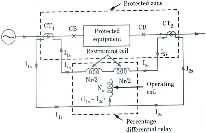
- B. Percentage differential relay :
- 1. If the operating torque produced by the operating coil exceeds the restraining torque produced by the restraining coil, the differential relay works.
- 2. Torque is related to the number of ampere turns. The relay will operate when the ampere turns of the working coil exceed the ampere turns of the restraining coil.
- C. Balanced voltage differential relay :
- 1. In this situation, the secondaries of the CTs are coupled in such a way that the secondary currents of the CTs oppose each other and their voltages are balanced under normal conditions and during external faults.
Hence no current flows in relay.
- 2. During internal fault, differential current is proportional to (I1 – I2) in case of single end fed system and is proportional to (I1 + I2) in case of double end fed system.
- 3. If the differential current flowing through the relay coil is higher than the pickup value the relay operates.
c. What is a carrier blocking scheme? Discuss its merits and demerits over other types of carrier aided distance protection.
Ans.
- A. Carrier blocking scheme :
- 1. In this design, the carrier signal is utilised to prevent the relay from operating in the event of an external problem.
- 2. When a failure occurs on the protected line section, the carrier signal is not transmitted.
- 3. The blocking strategies are especially well adapted to the protection of multiple-ended lines.
- 4. In this design, the zone 3 unit looks in the opposite way and sends a blocking signal to prohibit the zone 2 unit at the other end from operating due to an external malfunction.
- B. Merit: Even if the carrier signal fails, the relay will operate for end-zone failures in the blocking scheme. However, in the case of transfer trip schemes, the relay does not operate instantly for end-zone failures in the event of a carrier signal failure.
- C. Demerit: This scheme is not economical as compare to other scheme.
d. Discuss the recovery rate theory and energy balance theory of are interruption in a circuit breaker.
Ans.
- A. Slepian’s theory :
- 1. Slepian characterized the process as a race between dielectric strength and restraining voltage. There is a column of residual ionized gas after every current zero.
- 2. This may enable the arc to strike again by producing the necessary restriking voltage, and this voltage stress is sufficient to remove electrons from their atomic orbits, releasing a large amount of heat.
- 3. The rate at which positive ions and electrons recombine to produce neutral molecules is contrasted to the rate at which the restriking voltage rises in this hypothesis.
- 4. Recombination restores the dielectric strength of the gap. As a result, the rate of dielectric strength recovery is compared to the rate of restriking voltage rise.
- 5. If the restriking voltage rises more rapidly than the dielectric strength, gap space breaks down and arc strikes again and persists.
- B. Cassie’s theory :
- 1. Cassie proposed that arc re-establishment and arc interruption are both energy balancing processes. If the energy input to an area continues to rise, the arc restrikes; otherwise, the arc is interrupted.
- 2. The theory makes the following assumptions :
- i. Arc consists of a cylindrical column having uniform temperature at its cross section. The energy distributed in the column is uniform.
- ii. The temperature remains constant.
- iii. The cross-section of the arc adjusts itself to accommodate the arc current.
- iv. Power dissipation is proportional to cross sectional area of arc column.
The energy equation as expressed by Cassie is given by,
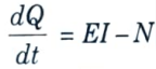
where, Q = Energy content / length of arc in cm
E = Volts / cm
I = Total current
N = Total power loss / cm
e. How can a quadrilateral distance relay be realized using a microprocessor ?
Ans.
- 1. The quadrilateral relay is utilized to protect EHV/UHV and ELD transmission lines because it has the least tendency for mal-operation due to heavy power swings, fault resistance, and overloads.
- 2. It is also appropriate for short and medium lines. Its characteristics can be tailored to simply enclose the fault area of the shielded line.
- 3. Using the same interface used for other types of distance relays, a microprocessor-based method can simply generate a quadrilateral feature.
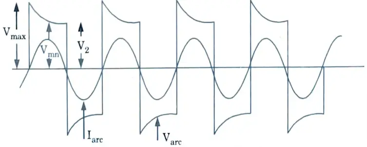
- 4. It has the flexibility to obtain a desired quadrilateral characteristic by simply providing the proper data. Quadrilateral characteristics are shown in Fig. 1(a) and (b).
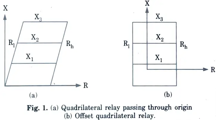
- 5. The block schematic diagram of the interface for realization of quadrilateral characteristic is shown in Fig. 2.
- 6. At the relay position, the microprocessor measures the resistance and reactance. The measured resistance and reactance values are compared to the predefined resistance and reactance values.
- 7. The predetermined resistance and reactance values are recorded in the memory in tabular form. These values are chosen to produce the required quadrilateral property.
- 8. To account for high fault resistance in the event of a short line, the characteristic can be simply expanded in the resistive direction using appropriate data in the memory.
- 9. The characteristic’s expansion in the resistive direction is independent of its reach in the reactive direction.
- 10. Corresponding to a particular value of the line reactance, Rl and Rh are the lower and higher limits of resistance on the characteristic curve shown in Fig. 1(a).
- 11. To obtain the desired quadrilateral characteristic, Rl and Rh for different values of line reactances are determined and stored in the memory.
- 12. The microcomputer first measures the line reactance X and compares it with X3 the predetermined value of the reactance for the third zone of protection.
- 13. If X is greater than X3 it goes back to the starting point and measures the same again.
- 14. If X is less than X3 it proceeds further to measure R, the resistance seen by the relay.
- 15. For the operation of the relay, the condition to be satisfied is Rl < R < Rh16. If X is less than X1, a tripping signal is sent to the circuit breaker instantaneously. If X is greater than X1 but less than X2, the tripping signal is sent after a predetermined delay. If X is greater than X2 but less than X3, a greater delay is provided.
Section 3 : Fault Detection
a. Find the output of CT having a transformation ratio of 100/5 and secondary resistance of 0.1 ohm. Its secondary terminals are connected to a relay whose burden is 4.5 VA. The resistance of the connecting leads is 0.15 ohm.
Ans. Given: Transformation ratio = 100/5, Secondary resistance = 0.1 Ω, Burden = 4.5 VA, Resistance of lead = 0. 15 ohm
To Find: Output VA of CT.
1. VA required to compensate connection lead resistance
= I2R= (5)2 x 0.15 = 3.75 VA
2. VA required for secondary side,
= I2R = (5)2 x 0.10 = 2.5 VA
3. VA required by the relay = 4.5 VA
4. Hence total VA output required for CT
= 3.75 + 2.5 + 4.5 = 10.75 VA
b. Describe briefly various method of fault detection.
Ans. A. Types of fault: In the electrical power system, the faults are classified into two types :
- 1. Symmetrical faults :
- i. A three-phase fault is called a symmetrical type of fault. In a 3-ɸ fault, all the three phases are short circuited.
- ii. The symmetrical faults are of two types,
- a. L-L-L
- b. L-L-L-G
- 2. Unsymmetrical faults :
- i. Single-phase to ground (L-G) fault: A short circuit between any one of the phase conductors and earth is called a single phase to ground fault.
- ii. Two-phase to ground (2L-G) fault: A short circuit between any two phases and the earth is called a double line to ground or a two-phase to ground fault.
- iii. Phase-to-phase (L-L) fault : A short circuit between any two phases is called a line to line or phase-to-phase fault.
B. Detection of fault: Detection of faults in components and their protection:
- 1. In generator, there are two types of faults:
- i. Stator faults.
- ii. Rotor faults.
- a. Protection of stator faults: By using percentage differential protection method.
- b. Protection of rotor faults: By using loss of excitation protection method.
- 2. In transformer, there are two types of faults :
- i. Internal faults.
- ii. External faults.
- a. Protection of internal faults: By using percentage differential protection method.
- b. Protection of external faults: By using time graded over current relays.
- 3. Protection of transmission line: By using distance protection method.
Section 4 : Sampling Comparator
a. An earth-fault starting relay has a setting of 30 %, and a current rating of 5 A. It is connected to a CT of ratio 500/5. Calculate pick up current in primary for which the earth fault relay operates.
Ans.
- 1. Current setting = 30 % = 0.3
- 2. Relay CT ratio = 500/5
- 3. Rated secondary current = 5 A
- 4. Pick-up current of relay = Rated secondary current x Current setting
= 5 x 0.3 = 1.5 A
- 5. For 1.5 A, the current in the primary of the CT is
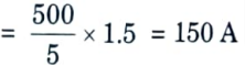
b. How a MHO characteristic is realized using a sampling comparator ?
Ans. Realization of MHO relay using a sampling comparator :
- 1. A MHO relay characteristic can be realized by comparing the instantaneous values of current at the voltage peak with the rectified voltage.
- 2. Fig. 3 shows the instantaneous value of the current at the moment of voltage maximum.
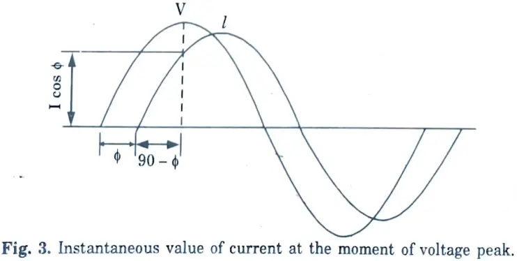
3. It is equal to I cos ɸ. For the operation of the relay, the condition to be satisfied is as follows.
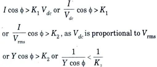
or M < K
4. If a design angle a is introduced while feeding the voltage and current signals to the relay, the above expression is modified and is given by
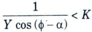
5. By changing a, a MHO characteristic can be shifted towards the R-axis to make it more tolerant to arc resistance.

or M < K
4. If a design angle a is introduced while feeding the voltage and current signals to the relay, the above expression is modified and is given by

5. By changing a, a MHO characteristic can be shifted towards the R-axis to make it more tolerant to arc resistance.
Section 5 : Protection of Bus Techniques
a. Explain the term overvoltage factor, protective ratio, protective angle, protective zone and coupling factor.
Ans.
- A. Overvoltage factor: It is defined as the peak overvoltage divided by the rated peak system-frequency phase voltage.
- B. Protective ratio: It is defined as the ratio of the induced voltage on a conductor with ground wire protection to the induced voltage on the same conductor if ground wire protection was not present.
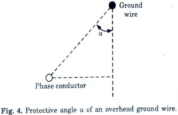
- C. Protective angle: The protective angle (𝜶) afforded by a ground wire is defined as the angle between a vertical line through the ground wire and a slanting line connecting the ground wire and the phase conductor to be protected. This angle is shown in Fig. 4.
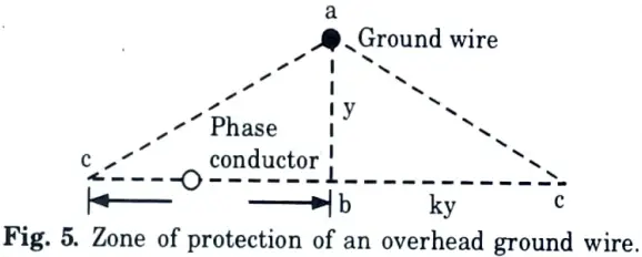
- D. Protective zone:
- 1. The protective zone is defined as the volume between the base plane cbc and the slanting planes ac, extending from the ground wire to the plane of the conductors.
- 2. Fig. 5 shows the cross-section of this volume. The plane ac cuts the base plane at c, at a distance ky from the point b, vertically under the apex a.
- 3. The ground wire is at a height ab =y above the base plane. The ratio ky/y = k is called the protective ratio.
- 4. The protective zone is sometimes called the protective wedge or protective shed.
- E. Coupling factor: The ratio of the induced voltage on the conductor to the ground wire voltage is known as the coupling factor.
b. What do you understand by the term protection of bus? Explain different types of protection of bus techniques.
Ans. A. Protection of bus (Bus bar): Busbar protection is a protection scheme meant to protect the busbar from electrical fault.
B. Types :
- a. Frame Leakage Protection of Busbar :
- 1. Metal supporting framework known as fault bus is earthed through a CT, When the fault is there, a contact between conductor and earth results,
- 2. This derives current through this CT and energizes the frame leakage relay.
- 3. The CT energizing the check relay is mounted in neutral earth of the transformer.
- 4. The contacts of check relay and frame leakage relay are in series.
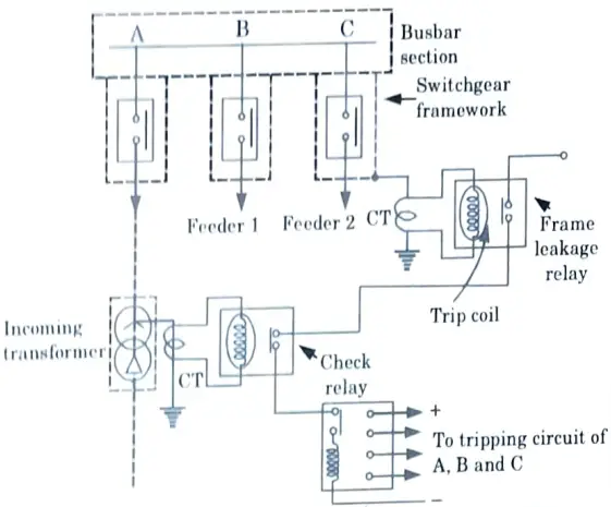
5. Thus before tripping circuit gets energized, both the relays operate and due to this, all the breakers will trip connecting the equipment to the busbar.
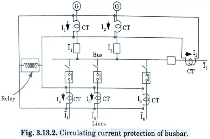
b. Circulating current protection of Busbar :
1. Ī1, Ī2, Ī3,….. Ī6 are the currents in the circuits connected to the busbar.
Under normal condition 𝚺I = 0 ⇒ Ī1 + Ī2 + …. + Ī6 = 0
Hence relays remain inoperative.
2. Under fault conditions,
Ī1 + Ī2 + …. + Ī6 = Īf
where Īf = Fault current
3. Hence, the relay operates.
c. High impedance differential protection of busbar :
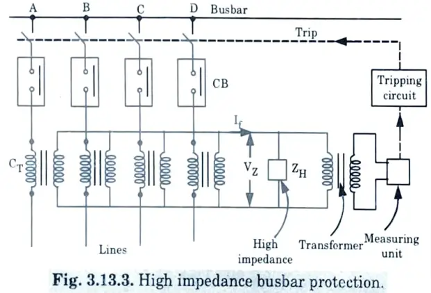
- 1. Under normal conditions, relay is inoperative. During fault conditions, unbalanced current exists. Such an out of balance current If flows through ZH causing a high voltage drop VZ across it. It is given to transformer.
- 2. A measuring unit is connected to the secondary of this transformer which measures this drop and trips the relay accordingly.
- 3. Main advantage is that as voltage drop is sensed, saturation of core of one of the CT has no effect on the protection scheme.
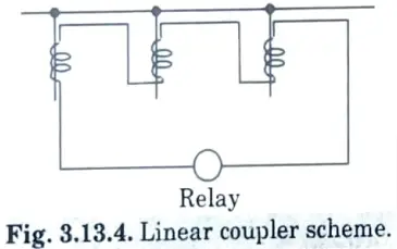
- d. Differential protection of bus using linear couplers :
- 1. The fundamental disadvantage of differential bus protection is the difference in saturation condition of different iron cored CT.
- 2. The differing magnetic conditions of iron cored CT may cause the relay to operate incorrectly during an external malfunction.
- 3. Using identical CT with large iron cores to avoid saturation with maximum fault currents does not alleviate the problem due to the presence of DC transient components swinging to their sluggish fading.
- 4. Whilst differential relay biassing improves stability significantly, it is not a perfect solution. To avoid the aforementioned challenges, a specific type of CT with no iron core, also known as a linear coupler, is used.
- 5. In case of linear couplers, secondary voltage is proportional to the primary current and the secondary windings of all coupler on the same bus section are connected in series to the relay as shown in the Fig. 3.13.4.
Section 6 : Air Blast Circuit Breaker
a. What are the advantages of an air blast circuit breaker over the oil circuit breaker?
Ans. The advantages of an air-blast circuit-breaker over an oil circuit-breaker are:
- 1. Elimination of fire hazard.
- 2. High speed operation.
- 3. Short and consistent are duration and therefore less burning of contacts.
- 4. Suitability for frequent operation.
- 5. Cheapness and free availability of the interrupting medium, chemical stability and inertness of air.
- 6. Reduced maintenance.
- 7. Facility for high speed reclosure.
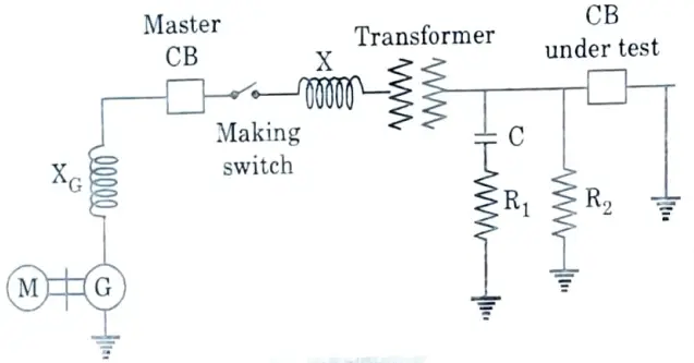
b. Discuss how making capacity and breaking capacity of a circuit breaker are tested in a laboratory type testing station.
Ans. A. Test for making capacity :
- 1. Close the master circuit breaker and the making switch first, then close the circuit breaker under test to trigger the short-circuit.
- 2. The rated making current is measured, which is the peak value of the first main loop of the short-circuit current wave.
B. Test for breaking capacity :
- 1. First of all, the master circuit breaker and the circuit breaker under test are closed.
- 2. Then the short-circuit current is passed by closing the making switch. The short-circuit current is interrupted by opening the breaker under test at the desired moment.
- 3. The following measurements are taken :
- i. Symmetrical breaking current
- ii. Asymmetrical breaking current
- iii. Recovery voltage
- iv. Frequency of oscillation and RRRV.
- 4. The circuit breaker must be capable of breaking all currents up to its rated capacity.
- 5. As it is not possible to test at all values of current, tests are performed at 10 %, 30 %, 60 % and 100 % of its rated breaking current.
Section 7 : Relay Reliability
a. How is relay reliability described ? What are the advantages of fast fault clearing ?
Ans. A. Relay reliability :
- 1. The primary characteristic of a protective relaying should be dependable. It denotes the relay system’s ability to work under predefined conditions.
- 2. Every component and circuit engaged in relay operation plays a vital function, and the dependability of a protective system is dependent on the reliability of numerous components such as circuit breakers, PTs, and so on.
- 3. The reliability is based on the design which can be achieved by factors like:
- a. Simplicity
- b. Robustness
- c. High contact pressure
- d. Good workmanship and careful maintenance.
B. Advantages of fast fault clearing :
- 1. The permanent damage to the equipment and components is avoided.
- 2. Chances of fire and other hazards are reduced.
- 3. Risk to the life of personnel is also reduced.
- 4. By quickly isolating the particular faulted section or components, the continuity of power supply is maintained in the remaining health section.
- 5. The transient state stability limit of the power system is greatly improved.
b. Write short notes on :
i. Level detectors
ii. Logic and training circuits
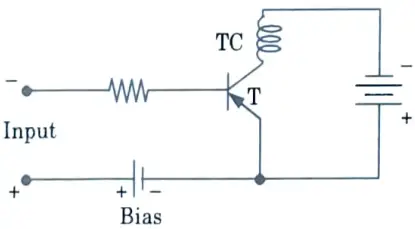
Ans. i. Level detectors :
- 1. Level detector circuits are employed in static relays as a final stage before the circuit breaker’s trip coil circuit.
- 2. The level detector gets its name from the fact that the circuit operates abruptly when the input level exceeds a certain threshold.
- 3. It is depicted in Fig., which depicts the operation of a level detector. To keep the transistor from conducting, the base is generally biassed positively.
- 4. If the input voltage is made to exceed the input bias in the opposite direction, i.e., the base is made negative with respect to its emitter, the transistor can be made to conduct or switch to operation.
ii. Logic and training circuits :
- 1. The logic operations conducted by the devices help to understand the notion of logic circuits in static relay. This simplifies difficult static relay operation.
- 2. All relays are bistable devices, which means they have two stable states: they function or they do not work.
- 3. As a result, Boolean algebra can be used to investigate and analyse protection schemes comprised of several relays.
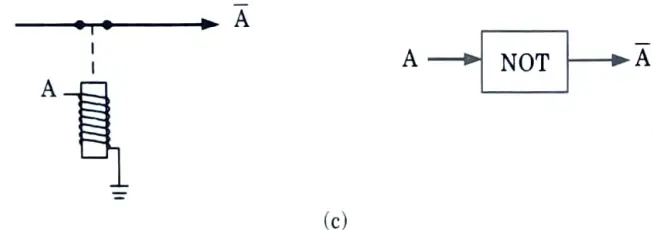
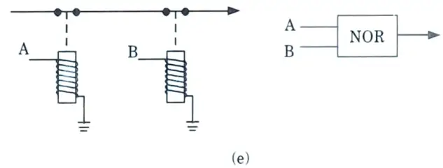
a. Relay logic:
- i. To provide a link between relay circuits and their logic processes, the basic operations mechanised by relays are depicted in Fig.
- ii. All connections are depicted in their natural, deenergized configuration. Each relay operation can thus be separated into simple switching functions, which can then be represented by an appropriate logic circuit.
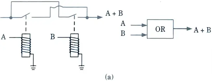
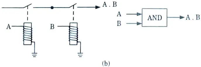
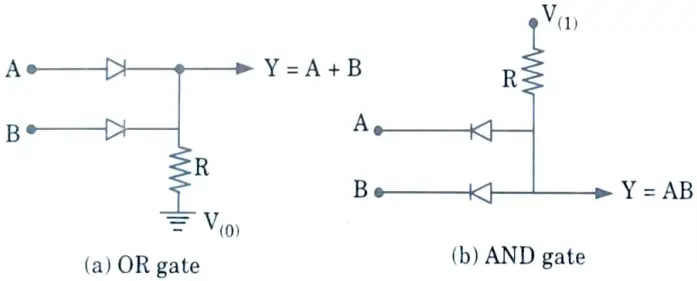
b. Diode logic (DL): The two stable states of the diode are conducting (i.e., forward bias) and non-conducting (i. e., reverse bias) states. Conventional diode OR gate (circuit) and AND gate are shown in Fig.
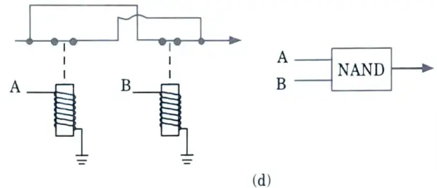
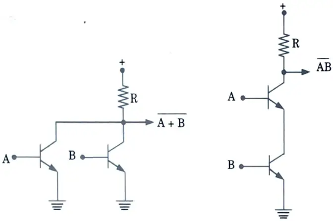
c. Transistor logic :
i. Logic circuits using transistors could be developed in two forms:
Resistor transistor logic (RTL)
Direct coupled transistor logic (DCTL).
ii. Basic NAND and NOR circuits based on DCTL are shown in Fig.
1 thought on “Power System Protection: Last year Question Paper Questions with Answer”