
“Additive Manufacturing: AKTU question paper with solutions” is a fantastic resource for B.Tech students, offering a wide selection of exam-style questions as well as thorough solutions for successful additive manufacturing preparation.
Dudes 🤔.. You want more useful details regarding this subject. Please keep in mind this as well.

Important Questions For Additive Manufacturing:
*Quantum          *B.tech-Syllabus
*Circulars           *B.tech AKTU RESULT
* Btech 4th Year
Section A: Short Question In Additive Manufacturing
a. Define the term layer based manufacturing.
Ans. Layer-based manufacturing, also known as rapid prototyping, is a set of techniques for rapidly fabricating a scale model of a physical part or assembly from three-dimensional CAD data by adding raw material in layers.
b. What is soft tooling ?
Ans. Soft tooling is a low-cost tooling process that enables manufacturers to produce medium to low numbers of parts at high speeds.
c. What is the difference between model and prototype ?
Ans.
| S. No. | Model | Prototype |
| 1. | It is used for display and demonstration of product. | It is used for performance evaluation and further improvement of product. |
| 2. | It contains only the exterior of the product. | It contains complete interior and exterior of the product. |
| 3. | It is cheap to manufacture. | It is expensive to manufacture. |
d. Differentiate between direct and indirect SLS system.
Ans.
| S. No. | Direct SLS System | Indirect SLS System |
| 1. | Direct SLS processes use metal powders directly without any binder. | Indirect SLS involves the use of a polymer binder to produce a green part. |
| 2. | Direct SLS eliminates the need for post-processing. | Post-processing is needed in indirect SLS to produce a high-density metal part. |
e. What is photopolymerization ?
Ans. Photopolymerization is a method of forming a linear or cross-linked polymer structure by initiating a polymerization reaction with light (visible or ultraviolet).
f. Explain the term powder bed fusion processes.
Ans. Direct metal laser sintering (DMLS), electron beam melting (EBM), selective heat sintering (SHS), selective laser melting (SLM), and selective laser sintering (SLS) are the four energy sources used in Powder Bed Fusion (PBF) (SLS).
g. Write a short note on STL file.
Ans. The STL file is derived from the word StereoLithography. STL files are generated from 3D-CAD data within the CAD system.
h. Write a brief note on STL file resolution.
Ans. The STL file is a data format file that uses connected triangles to construct a solid model’s surface geometry. The higher the resolution, the smaller the triangles, which means that more triangles will be used to construct the surface of the 3D model, which will show more detail. A low resolution will result in larger triangles and less information on the model’s surface. As a result, selecting the right STL file resolution is critical in producing a decent 3D printed object.
i. Define 3D printer technology used in additive manufacturing.
Ans. In 3D printing technology, a design of an object is created using software, and the object is created by the 3D printer by adding layer upon layer of material until the shape of the object is completed.
j. How additive manufacturing helps in aerospace and bio medical applications ?
Ans. Application in Aerospace :
- 1. The aerospace sector uses AM techniques due to the small series and frequent specific design needs of its clients.
- 2. Additive manufacturing techniques have been found to assist lower costs and lead times.
Application in Bio Medical :
- 1. AM has numerous applications in biomedicine due to its ability to create complex customised parts with great ease, flexibility, and using a variety of biomaterials.
- 2. AM has transformed the biomedical profession by printing personalised patient-specific implants for various body parts, as well as prosthetics, surgical equipment, and medical gadgets.
Section B : Long Questions Additive Manufacturing
a. Write a descriptive note or distinction between CNC and AM.
Ans.
| Parameter | AM Machining | CNC Machining |
| Material | AM includes development of polymeric material, waxes and paper laminates. | CNC used for machining soft materials or medium density fiber board, machinable foams and machinable waxes etc. |
| Speed | Higher, takes few hours to make part. | Lower, takes weeks to develop same part. |
| Complexity | Complex operation | Easy operation |
| Efficiency | Higher | Lower |
| Accuracy | More accurate | Comparatively less |
| Programming | In AM machine the part won’t be built properly if in correct programming is done | Incorrect programming can badly damage the machine and may even be safety risk. |
| Process | It is an additive process. | It is subtractive process. |
b. Why is additive manufacturing important ? Also classify additive manufacturing systems.
Ans. A. Importance of Additive Manufacturing :
- 1. The significance of additive manufacturing lies not in its ability to replace conventional machining processes, but in its ability to expand production capacities.
- 2. Apart from demonstrating its effectiveness for making pieces that are precise enough and resilient enough for end-use application, additive manufacturing promises to deliver following advantages :
- i. Design freedom
- ii. Low-quantity economy
- iii. Material efficiency
- iv. Predictable production
B. Classification of Additive Manufacturing Systems :
- 1. Binder Jetting
- 2. Directed Energy Deposition (DED)
- 3. Powder Bed Fusion (PBF)
- 4. Sheet Lamination
- 5. Material Extrusion
- 6. MaterialJetting
- 7. Vat Photopolymerization
c. What are the materials used in rapid prototyping ?
Ans. Materials used in rapid prototyping are as follows :
- i. Urethane Resins: A thermosetting polymer that is typically poured into a mold to make prototypes.
- ii. Silicones: A silica and oxygen compound that comes in many forms, including resins and solid or liquid rubbers.
- iii. Glass Fiber: Very fine fibers of glass that can be adhered to a model or other materials to provide insulation or reinforcement.
- iv. Carbon Fiber: Very fine fibers of carbon that can be woven together into a fabric or added to other materials to provide reinforcement.
- v. Thermoplastics: A type of plastic that can be melted down and molded or 3D printed into certain shapes.
- vi. Metals: Aluminum and steel are common prototyping options.
d. Discuss in detail about the problems associated with STL files used in additive manufacturing.
Ans. Following are typical problems that are associated with STL files :
- A. Unit Changing:
- 1. The units used in the STL format are not explicitly stated.
- 2. Because machines in the United States usually use imperial measures and the majority of the world uses metric, certain files may seem scaled.
- 3. Because the machine’s physical origin is in the bottom left-hand corner, all triangle coordinates in an STL file must be positive.
- 4. Nevertheless, this may not be the case for a specific part created in the CA system, in which case some STL file offset modification may be required.
- B. Vertex to Vertex Rule:
- 1. Each triangle must share two of its vertices with triangles adjacent to it.
- 2. This means that a vertex cannot intersect the side of another.
- 3. This is not explicitly stated in the STL file description.
- 4. Therefore STL file generation may not adhere to this rule.
- C. Leaking STL files:
- 1. STL data files should construct manifold entities according to Euler’s rule for solids.
- 2. If this rule does not hold then the STL file is said to be leaking.
- 3. Due to this the file slices will not represent the actual model.
- D. Degenerated Facets:
- 1. These facets normally occur due to numerical truncation.
- 2. A triangle may be so small that all three points virtually coincide with each other.
- 3. After truncation, these points lay on top of each other causing a triangle with no area.
e. With an example, discuss the type of materials available for additive manufacturing and their suitability in product development.
Ans. AM process uses materials of classes, namely plastics, metals, and ceramics.
- A. Plastics :
- 1. Plastics were the first group of materials to be processed by AM.
- 2. Plastics provide the biggest part of materials to be processed by AM.
- 3. Materials used for stereolithography are acrylic or epoxy resins.
- 4. For plastic laser sintering, polyamides are the preferred material.
- 5. Polyamides are very strong and heat and chemical resistant polymers.
- 6. Another group of materials for laser sintering are polyamide-coated particles made from almost any arbitrary material.
- 7. Amorphous structured polystyrene is also used as a material for laser sintering.
- B. Metals :
- 1. The most frequently used methods for AM of metals are sintering.
- 2. The material comes as powders with a primary particle size of 20-30 μm.
- 3. The materials are very similar to the materials used for laser coating with filler material.
- 4. Therefore, a wide variety of qualities of material is available.
- 5. However, the qualification of the material must be evaluated in-house.
- 6. AM machine manufacturers also provide material data sheets based on proven parameters.
- 7. For AM of metals, stainless steel, tool steel, CoCr-alloys, titanium, magnesium, aluminum, gold and silver are available.
- C. Ceramics :
- 1. AM ceramic materials are used in specialized niche of layer manufacturing technologies.
- 2. Laser sintering is the preferred process.
- 3. Layer Laminate Manufacturing (LLM) is basically suitable to fabricate ceramic foils. 4. For AM of ceramics, aluminum oxide, Al2O3, silicon dioxide or silica, SiO2, zirconium oxide, ZrO2, silicon carbide, SiC are available.
Section 3 : 3D Keltool Process
a. Describe the steps involved in production of inserts using the 3D keltool process with neat sketches.
Ans. The production of inserts employing the 3D Keltool process involves the following steps :
- 1. Creating the master patterns for the core and cavity.
- 2. Making RTV Silicone rubber moulds from the patterns.
- 3. Filling the silicon rubber moulds with a metal mixture (powdered steel, tungsten carbide, and polymer binder with particle sizes of roughly 5 um) to make green parts (powdered metal held together by polymer binder) and replicating the masters.
- 4. Sintering the metal particles together by firing the green sections in a furnace to remove the plastic binder.
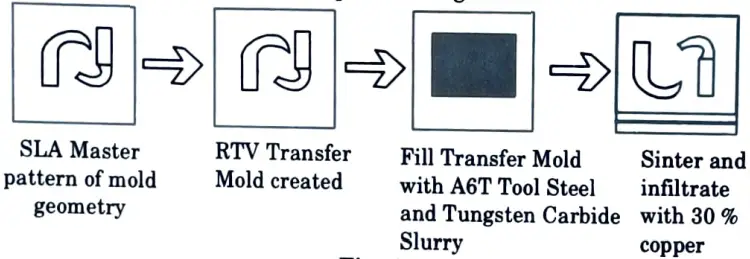
- 5. Infiltrating the sintered parts (70 % dense inserts) with copper in a second furnace cycle to fill the 30 % void space.
- 6. Finishing the core and cavity.
b. Define additive manufacturing. Explain the basic methodology involved in it. Also explain time compression engineering with the help of block diagram.
Ans. A. Additive Manufacturing: It is a layer-based automated fabrication process for making scaled 3-dimensional physical objects directly from 3D-CAD data.
B. Methodology of AM : Following are the 8 steps in additive manufacturing :
- Step 1: Conceptualization and CAD
- 1. Creating an idea for how the product will look and function is the first step in any product development process.
- 2. Every additive manufacturing parts must begin with a software model that properly characterises the exterior geometry.
- 3. The use of any competent CAD solid modelling software is required.
- 4. The output must be a three-dimensional solid or surface representation.
- Step 2: Conversion to STL
- 1. The STL file format, which has become a de facto standard, is supported by nearly every AM machine.
- 2. Almost every CAD system can now generate such a file format.
- 3. STL is a straightforward means of defining a CAD object based just on its geometry.
- 4. This file describes the original CAD model’s external closed surfaces.
- Step 3: Transfer to AM Machine and STL File Manipulation
- 1. Once the STL file has been created it must be transferred to the AM machine.
- 2. After that some general manipulation is done on the file.
- 3. These manipulations ensures that STL file is of the correct size, position, and orientation for building.
- Step 4: Machine Setup
- 1. The AM machine must be properly set up prior to the build process.
- 2. AM machines have some setup parameters that are specific to that machine or process.
- 3. Machine setup relates to the build parameters like material constraints, energy source, layer thickness, timings, etc.
- Step 5: Build
- 1. Building the part is computer-controlled automated process.
- 2. The AM machine can largely carry on without supervision.
- 3. Only superficial monitoring of the machine needs to take place at this time to ensure no errors have taken place.
- Step 6: Removal and Cleanup
- 1. After the AM machine has finished the build, the pieces must be removed from the build platform.
- 2. Part removal requires some competence because mishandling of parts can result in damage.
- 3. All procedures necessitate some level of cleanup.
- 4. The cleanup stage is the first stage of post-processing.
- Step 7: Post-processing
- 1. Parts may require extra cleaning after being removed from the machine.
- 2. Post-processing refers to the phases of cleaning up the pieces in preparation for application.
- 3. This may include abrasive finishing such as polishing and sandpapering, as well as the application of coatings.
- 4. This stage of the procedure is highly application dependent.
- Step 8: Application
- 1. Following post-processing, parts are ready for use.
- 2. However, they may also require additional treatment before they are acceptable for use.
- 3. For example, they may require priming and painting to give an acceptable surface texture and finish.
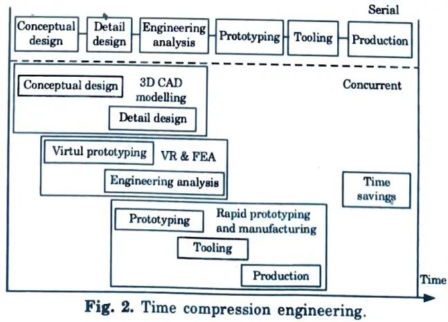
C. Time Compression Engineering :
- 1. 3-D computer-aided design modelling is the primary enabling technology for time compression engineering.
- 2. If multiple design and production operations are carried out concurrently, the overall product development time can be reduced.
- 3. This can also help engineers to be more creative by allowing for more design iterations (Fig.).
Section 4 : Additive Manufacturing Processes
a. Discuss the role of Computer Aided Design technology in the development of additive manufacturing processes. Enlist the role of other associated technologies for further improvement of AM systems.
Ans. A. Role of Computer Aided Design Technology in the Development of AM :
- 1. CAD technology contains knowledge about a specific sort of product, such as geometric, electrical, thermal, dynamic, and static characteristics.
- 2. CAD systems may include rules that govern such behaviours, allowing the user to concentrate on design and functioning rather than worrying about whether or not a product will work.
- 3. CAD also enables the user to concentrate on minor details of a large product while keeping data integrity and ordering it to understand how subsystems interact with the rest of the product.
- 4. Additive Manufacturing technology primarily makes use of the output from mechanical engineering, 3D solid modeling CAD software.
- 5. Not all CAD systems can produce output suitable for layer-based AM technology.
- 6. Currently, AM technology focuses on reproducing geometric form.
- 7. So the CAD systems that produce such forms are used in AM technology.
- 8. CAD developed quickly due to the the demands set by Computer-Aided Manufacture (CAM).
- 9. CAM converts the virtual models developed in CAD into the physical products.
- 10. CAM systems produce the code for numerically controlled (NC) machinery which would then fabricate the desired features on a stock material.
- 11. NC machining, therefore, only requires surface modeling software.
- 12. All early CAM systems were based on surface modeling CAD.
- 13. AM technology was the first automated computer-aided manufacturing process that truly required 3D solid modeling CAD.
- 14. Solid modeling CAD ensures that all models made have a volume and, therefore, by definition are fully enclosed.
B. Role of other Technology :
- 1. Lasers
- 2. Printing Technologies
- 3. Programmable Logic Controllers
- 4. Materials
- 5. Computer Numerically Controlled Machining
b. Compare wireframe, surface and solid models with suitable examples.
Ans.
| S. No. | Parameters | Wireframe Model | Surface Model | Solid Model |
| 1. | Computer memory space required | Low | Moderate | Large |
| 2. | Entities used | Point, line, circle, arc, ellipse, synthetic curves such as bezier, Hermite, B-spine etc. | Plane, revolved, ruled, tabulated, tree form surfaces. | Solid primitives such cone, cube, wedge, sphere etc. |
| 3. | Input data required | More | Moderate | Less |
| 4. | Automatic orthographic, perspective, isometric view generation | Impossible | Impossible | Easily possible |
| 5. | NC code generation | Not possible | Automatic possible | Automatic possible |
| 6. | Rendering, shadow effect | Not possible | Possible | Possible |
| 7. | Cross, sectioning | Not possible done manually | Not possible | Possible done automatically |
Section 5 : Directed Energy Deposition (DED) Processes
a. Explain the working principle of Directed Energy Deposition (DED) processes with neat sketch. What are the process parameters of DED ?
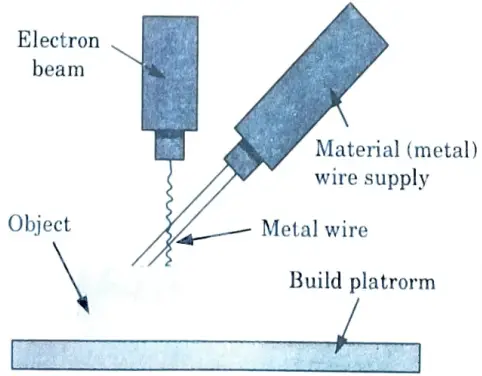
Ans. A. Directed Energy Deposition (DED) :
- 1. A 4 or 5 axis arm with nozzle moves around a fixed object.
- 2. Material is deposited from the nozzle onto existing surfaces of the object.
- 3. Material is either provided in wire or powder form.
- 4. Material is melted using a laser, electron beam or plasma arc upon deposition.
- 5. Further material is added layer by layer and solidifies, creating or repairing new material features on the existing object.
B. Process Parameters of DED :
- 1. DED machines are flexible platforms.
- 2. A DED users must identify the correct process parameters for their application and material.
- 3. Optimum process parameters are material and application dependent.
- 4. Important process parameters include track scan spacing, powder feed rate, beam traverse speed, beam power, and beam spot size.
- a. Powder Feed Rate :
- i. Increasing powder feed rate increases deposit thickness.
- b. Beam Power :
- i. Raising beam power thickens the deposit.
- ii. To control the solidification rate, the melt pool size can be monitored and then controlled by altering the laser beam strength dynamically.
- c. Beam Traverse Speed :
- i. Decreasing beam traverse speed increases deposit thickness.
- ii. To control deposit thickness, beam traverse speed can be dynamically changed based upon sensor feedback.
- d. Track Scan Spacing :
- i. Scan patterns have a significant impact on part quality.
- ii. We can reduce residual stress development by altering the scan orientation from layer to layer.
- iii. When the scan speed increases, so does the input beam energy, resulting in a smaller melt pool on the substrate and faster cooling.
b. Define powder bed fusion processes. Discuss the solid-state sintering and chemically induced sintering with suitable examples.
Ans. A. Powder Bed Fusion Processes :
- 1. Direct metal laser sintering (DMLS), electron beam melting (EBM), selective heat sintering (SHS), selective laser melting (SLM), and selective laser sintering (SLS) are the four energy sources used in Powder Bed Fusion (PBF) (SLS).
- 2. PBF processes melt and fuse material powder together using either a laser or an electron beam.
- 3. The powder bed fusion method employs two chambers, the build and powder chambers, as well as a coating roller.
- 4. The coating roller moves and spreads the powder material across the build chamber to deposit a thin layer of powder to construct the items.
- 5. The energy source next melts the metal powder base’s deposited top layer.
- 6. After that layer has been scanned and fused, the build platform is lowered and the powder chamber is elevated at the same time.
- 7. The process is repeated till the object is finished.
B. Solid-State Sintering :
- 1. The fusing of powder particles in their solid state at high temperatures is referred to as solid state sintering.
- 2. Diffusion between powder particles is the sintering mechanism.
- 3. As particles fuse at high temperatures, the overall surface area and consequently surface energy are reduced.
- 4. The rate of sintering slows as the total surface area of the powder bed decreases.
- 5. High sintering temperatures are required to produce very low porosity levels.
- 6. The application of external pressure accelerates the sintering process.
- 7. The surface area to volume ratio of a set of particles is directly proportional to the driving force for sintering.
- 8. The stronger the pushing force, the bigger the surface area to volume ratio.
- 9. As a result of the stronger pushing force, smaller particles sinter faster than bigger particles.
- 10. In AM, the faster it takes to build a layer, the more cost-effective the process becomes.
- 11. Because sintering takes longer to fuse, few AM methods use it as the principal fusion mechanism.
C. Chemically Induced Sintering :
- 1. It employs thermally triggered chemical reactions to produce a by-product that binds the particles together.
- 2. These chemical reactions occur when two types of powders interact or when powders interact with atmospheric gases.
- 3. Ceramic materials are primarily used for this fusing mechanism.
- 4. A laser can be used to cause high-temperature structural ceramic mixes to react for chemically induced sintering between powders.
- 5. In this situation, raw ingredients are pre-mixed and laser-heated.
- 6. By combining laser energy with chemical reaction energy, high-melting-temperature structures can be created at comparatively modest laser energies.
- 7. Post-process infiltration is frequently required in chemically induced sintering to acquire characteristics useful for most applications.
- 8. The cost and time associated with post-processing have limited the adoption of chemically induced sintering in commercial machines.
Section 6 : STL File Generation
a. What is the important requirement that must be fulfilled during STL file generation ?
Ans.
- 1. STL is a basic means of representing a CAD model based just on its geometry.
- 2. It works by eliminating any building data, modelling history, and so on, and then approximating the model’s surfaces with a series of triangular facets.
- 3. The minimum size of these triangles can be specified, and the goal is to ensure that the models made have no apparent triangles on the surface.
- 4. The triangle size is determined by the shortest distance between the plane represented by the triangle and the surface it is meant to represent.
- 5. In other words, a good rule of thumb is to keep the minimum triangle offset less than the AM machine’s resolution.
- 6. This is the most important requirement that must be fulfilled during STL file generation.
b. Explain STL repair and STL manipulation with respect to magics AM software.
Ans. A. STL Repair :
- 1. Repairing STL files is similar to mending photographs. Picture editing software frequently has an automated option that fixes an image with a single click.
- 2. The same holds true for STLs. There are repair tools available to auto repair files, and while they can work, they frequently do not, sometimes with surprising outcomes (like when holes that should be part of a model get filled in).
- 3. Some technologies allow thorough analysis and fine control over fixes, but in extreme circumstances, editing the original 3D model may be the only choice.
- 4. A typical STL repair steps are as follows :
- i. Auto mesh repair.
- ii. Manual mesh repair.
- iii. Re-modeling.
- iv. Optimization.
B. STL Manipulation :
- 1. STL manipulation tools are utilised on an AM machine for activities such as scaling, changing orientation, and merging with other STL files.
- 2. STL modification tools on an AM machine are also used to relocate a part or create a duplicate of the original part.
- 3. The support structures are also created on the AM machine.
Section 7 : AM Systems
a. Write short notes on :
i. Object Quadra system.
ii. Thermal jet printer.
Ans. i. Object Quadra System :
- 1. The Quadra system is based on cutting-edge ink-jet printing technology.
- 2. The printer uses a proprietary photopolymer created in-house by object that does not require post-cure or post-processing.
- 3. The material is given by a sealed cartridge, which is simple to install and replace.
- 4. The support material readily separates from the model body, leaving no contact spots or flaws on the model.
- 5. The material characteristics of Quadra-printed objects are unrivalled by machines in its class and price range.
- 6. The Quadra prints in a resolution of 600 dpi, with a layer thickness of 20 microns, and builds parts up to a maximum size of 11″ x 12″ x 8″.
ii. Thermal Jet Printer :
- 1. The construction material (thermoplastic) and support material (wax) are melted inside two heated reservoirs before the inkjet printing process begins.
- 2. Each of these ingredients is fed into an inkjet print head, which moves in the X-Y plane and shoots tiny droplets to the necessary locations to build one layer of the part.
- 3. Both the construction and support materials immediately cool and solidify. After completing a layer, a milling head glides across the layer to smooth the surface.
- 4. The particle collection vacuums away the particles produced by this cutting action.
- 5. The lift then lowers the build platform and portion, allowing the next layer to be constructed.
- 6. After this process is repeated for each layer and the part is complete, the part can be removed and the wax support material can be melted away.
b. Explain in brief the applications of AM systems in various industries with examples.
Ans. Applications of AM systems in various industries are as follows :
A. Application in Foundry & Casting :
Foundry :
- 1. Foundries use AM processes to receive prototypes and samples of the product.
- 2. They also use AM processes to make cores and cavities for production.
- 3. If cheap and quickly available sample is needed then 3D printing is preferred.
- 4. The application level is rapid prototyping/solid imaging.
Casting :
- 1. AM provides novel impulses primarily for sand casting and investment casting because the required lost cores and cavities can be created rapidly and easily.
- 2. The increased complexity of the AM parts enables the realisation of shapes that cannot be realised manually or with special tools.
- 3. For sand casting processes, AM supports two trends: the digitization of the entire process and the increasing complexity of cast parts.
- 4. Today’s foundry manufacturing chain is entirely CAD-based, and all data may be accessed straight from the CAD model.
- 5. Using AM techniques, cores and cavities for high precision parts can be manufactured in any quantity directly from digital data.
- 6. Investment casting has traditionally been associated with the lost wax technique, although today “wax” refers to any thermoplastic substance that performs similarly to wax.
- 7. Wax printers generate wax-like formations that can be resolved using heat.
B. Application in Jewellery :
- 1. The jewellery industry is still mostly based on conventional fabrication methods.
- 2. These approaches take too much time and, in some situations, are inefficient when compared to the ultimate product’s quality.
- 3. The incorporation of new technologies may be a solution to these problems.
- 4. Additive manufacturing allows for the creation of novel products and geometries while simultaneously lowering manufacturing time, energy, and labour costs.
- 5. A laser melting machine may make a complex piece of jewellery using additive manufacturing.
- 6. Many AM machines are capable of growing jewellery pieces from precious metal powder.
- 7. The true promise of the additive manufacturing method lies in designs that are difficult or impossible to produce using standard casting procedures.
C. Application in Art :
- 1. Artists were among the first to take advantage of the freedom of infinite geometries provided by AM methods.
- 2. Because of its weight, metal is considered more valuable than plastic by artists.
- 3. AM can successfully assist the creative work of artists.
- 4. To create a sculpture, a hand-made model can be scanned and converted into an AM part.
- 5. This master can be worked out manually to represent the artist’s intention, and then converted into a small series produced of brass using a wax pattern.
- 6. AM can also be used to create human sculptures.
- 7. 3D body scanning makes it relatively simple to gather the 3D data required for the creation of human sculptures.
1 thought on “Additive Manufacturing: AKTU Question Paper with Solution”