With our AKTU question paper and solution, you may enter into the interesting the world of Sensor and Transducers. Engaging notes make learning about these incredible gadgets enjoyable and approachable for young brains.
Dudes 🤔.. You want more useful details regarding this subject. Please keep in mind this as well.

Important Questions For Sensor and Transducers:
*Quantum          *B.tech-Syllabus
*Circulars           *B.tech AKTU RESULT
* Btech 3rd Year
Section A: Sensor and Transducers Short Questions with Answer
a. Describe the functioning of LVDT.
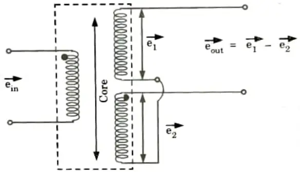
Ans. 1. As the primary is connected to an AC source so alternating current and voltages are produced in the secondary of the LVDT. The output in secondary S1 is e1 and in the secondary S2 is e2. So the differential output is

b. Define piezoelectric sensors.
Ans.
- 1. A piezoelectric transducer (also known as a piezoelectric sensor) is a device that uses the piezoelectric effect to transform energy into an electrical charge in order to measure changes in acceleration, pressure, strain, temperature, or force.
- 2. A crystal is elastically bent when pressure is applied to it. This deformation causes an electric charge flow (which lasts for a period of a few seconds).
c. How can you say that proximity sensors are indispensable in industrial applications?
Ans. As proximity sensors have so many uses, they are essential.
d. What are RTDs?
Ans. A resistance thermometer, also known as a Resistance Temperature Detector (RTD), is a device that measures the resistance of pure electrical wire to estimate the temperature. This wire is known as a temperature sensor.
e. Charge coupled device: Explain.
Ans.
- 1. A charge-coupled device (CCD) is a type of image capture technology used in everything from digital astrophotography to machine vision inspection.
- 2. A CCD sensor is a silicon chip with a grid of photosensitive spots.
f. How complementary metal-oxide semiconductor type of imaging sensors work ?
Ans. The charge from the photosensitive pixel is transformed to a voltage at the pixel site in a complementary metal oxide semiconductor (CMOS) sensor, and the signal is multiplexed by row and column to many on-chip digital-to-analog converters (DACs).
g. Which type of ADC is widely used ? Why?
Ans. The most widely used ADC is flash ADC since it is the fastest type available.
h. What is the role of timers in data acquisition systems ?
Ans.
- 1. The counter and timer functions calculate the frequency or period of an input signal, as well as the total number of pulses or cycles recorded in a certain time period.
- 2. A counter also counts the absolute number of input events, pulses, or cycles within a specified time period and outputs the overall number as a result.
- 3. A timer measures the amount of time it takes for a preprogrammed number of input signal cycles to occur.
i. What is self-calibration in smart sensors ?
Ans.
- 1. Self-calibration refers to altering a sensor parameter during manufacture, which can be gain, offset, or both.
- 2. Self-calibration is the process of adjusting the divergence of the sensor’s output from the target value while the input is at its smallest, or it can be an initial gain adjustment.
- 3. Calibration is required since their modifications typically vary over time, necessitating the removal and recalibration of the device.
- 4. If recalibration of the units is difficult once they are in service, the manufacturer over-designs to ensure that the item operates within specification throughout its service life.
- 5. Smart sensors solve these issues since they have a built-in microprocessor with correction functions stored in their memory.
j. How smart sensors are self-testing and self-communicating ?
Ans. Self-testing:
- 1. Some smart sensors can measure more than one physical or chemical variable at the same time.
- 2. A single intelligent sensor can measure pressure, temperature, humidity, gas flow, infrared, chemical reaction surface acoustic vapour, and other parameters.
Self-communicating:
- 1. Communication is the process of exchanging or transferring information, which a smart sensor can readily perform.
- 2. This is quite useful because the sensor can broadcast information about its own condition as well as measurement uncertainty.
Section B: Sensor and Transducers Long Questions with Answers
a. What are the benefits of measurement of displacement using potentiometer ? Give a detailed report.
Ans.
- 1. They are cheap.
- 2. It is simple to use and helpful in a wide range of applications with light requirements.
- 3. It produces enough output to avoid the need for additional amplification.
- 4. The potentiometer has a high efficiency.
- 5. The resolution of cermet and metal film potentiometers is limitless.
b. Discuss vibration sensors with respect to their methodology of working.
Ans. 1. Accelerometer: Accelerometers are devices that measure a structure’s vibration or acceleration of motion.
2. Strain gauge:
- i. A strain gauge is a sensor whose resistance changes in response to applied force.
- ii. It translates force, pressure, tension, weight, and so on into an electrical resistance change that can subsequently be measured.
3. Eddy-current:
- i. Eddy-current sensors are non-contact devices that measure a conductive component’s position and/or change of position. Magnetic fields are used by these sensors.
- ii. The sensor has a probe that generates an alternating current at its tip.
c. Write short notes on advantages of machine vision.
Ans. Advantages of machine vision:
- 1. It improves quality.
- 2. It boosts productivity.
- 3. It increases production flexibility.
- 4. It cuts down on machine setup time.
- 5. It provides thorough and accurate information.
- 6. It improves process control.
- 7. It reduces the cost of capital equipment.
- It reduces production costs.
- 9. It improves inventory control.
d. Discuss types of amplifiers with respect to their amplification parameter.
Ans. There are many types of amplifiers used in signal conditioning including the following:
- 1. Voltage amplifiers: They have a unity gain, therefore the output signal is a replica of the input signal. This sort of amplifier is mostly utilised as an impedance matching device.
- 2. Isolation amplifiers: They are specifically intended to isolate excessive DC levels from the data gathering equipment while still passing the comparatively tiny AC or differential signal. Electrical isolation exists between the inputs and outputs.
- 3. Instrumentation amplifiers: These are differential amplifiers designed for use with direct current signals. They have high gain, a high Common Mode Rejection Ratio (CMRR), and a high input impedance.
- 4. Sample-and-hold amplifiers: These amplifiers immediately freeze the analogue voltage. The HOLD instruction is delivered during this operation, and analogue voltage is available for an extended length of time.
- 5. Current amplifier: An amplifier that raises the provided input current, as the name implies. It has a low input impedance and a high output impedance.
- 6. Voltage amplifier: An amplifier that multiplies a given voltage to produce a higher voltage output. It has a high input impedance and a low output impedance.
- 7. Transconductance amplifier:An amplifier that modifies output current in response to changes in input voltage.
- 8. Transresistance amplifier: An amplifier with variable output voltage and variable input current. It is also referred to as a converter of current to voltage.
- 9. Operational amplifiers (Op-Amps):
- i. An op-amp is an integrated circuit with differential input that functions as a voltage amplifier.
- ii. It has a single, extremely high gain output but both positive and negative inputs. Op-amps were initially made with valves.
- 10. Valve (or) vacuum tube amplifiers:
- i. A valve (or) vacuum tube amplifier is one that employs vacuum tubes to produce an increased power or voltage output.
- ii. Originally of the valve variety, op-amps were eventually supplanted by integrated circuits (ICs), at least in smaller applications.
- iii. They continue to be used in high power applications due to their low cost and great output quality. They are employed in applications involving radar, the military, high power radio, and UHP transmitters.
- 11. Transistor amplifiers:
- i. A transistor amplifier is a high output, multi-configuration amplifier with a working base made of transistors.
- ii. They include Metal Oxide Semiconductor Field-Effect Transistors (MOSFETs) and Bipolar Junction Transistors (BJTs).
- 12. Klystron:
- i. An amplifier for high radio frequencies that uses a specific kind of linear beam hoover tube.
- ii. It belongs to the category of microwave amplifiers and is extremely precise and used in large-scale operations.
- 13. Instrument amplifiers: Amplifying devices that are especially made for music, voice, or sound. used mostly in applications involving musical instruments.
- 14. Distributed amplifiers: Distributed amplifiers are amplifiers that momentarily partition the input and independently amplify each segment via transmission lines. They are frequently discovered in oscilloscopes.
e. What are the strategies for industrial robots’ adaptation in smart sensor applications?
Ans.
- 1. Force torque sensor
- 2. Collision detection sensor
- 3. Safety sensors
- 4. Part detection sensors
- 5. 2D vision
- 6. 3D vision
- 7. Others
Section 3: LVDT Based Diaphragm and Piezoelectric Sensor
a. Explain measurement of pressure using LVDT based diaphragm and piezoelectric sensor with suitable diagrams.
Ans. A. Measurement of pressure using LVDT based diaphragm:
- 1. The diaphragm pressure gauge measures the difference between an unknown pressure and a reference pressure by measuring the elastic deformation of the membrane that makes up the diaphragm (as opposed to using a liquid level).
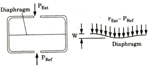
- 2. A typical diaphragm pressure gauge contains a capsule divided by a diaphragm, as shown in Fig.
- 3. One side of diaphragm is open to the external targeted pressure, PExt, and the other side is connected to a known pressure, PRef The pressure difference PExt-PRef mechanically deflects the diaphragm.
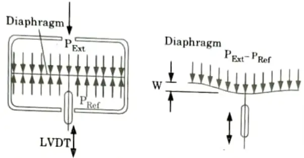
- 4. The membrane of the diaphragm is connected to LVDT as shown in Fig.
- 5. A displacement is applied to the core or primary Coil of the LVDT as a result of pressure being applied to the diaphragm. As a result, the LVDT’s secondary winding induces a voltage. The pressure that is applied immediately affects the induced voltage.
B. Measurement of pressure using LVDT based piezoelectric sensor:
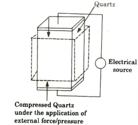
- 1. A device that utilises the piezoelectric effect to monitor changes in acceleration, pressure, strain, temperature, or force by turning this energy into an electrical charge is known as a piezoelectric transducer (also known as a piezoelectric sensor).
- 2. A crystal is elastically bent when pressure is applied. This deformation causes an electric charge to flow (which lasts for a period of a few seconds).
- 3. The electric signal that is produced can be measured to determine the pressure that was applied to the crystal.
- 4. These sensors are employed to measure quickly changing pressures brought on by blasts, explosions, pressure pulsations (from rocket motors, engines, compressors), or other causes of shock or vibration. They are unable to detect static pressures.
- 5. Piezoelectric sensors are used to measure dynamic forces such oscillation, impact, and high-speed compression or tension as well as pressure, acceleration, and these forces.
- 6. It includes piezoelectric ionic crystal components like Quartz, as depicted in Fig. These materials stretch or contract when pressure or force is applied.
- 7. The charge over the substance shifts and redistributes during this operation. The material’s faces become positively and negatively charged, respectively.
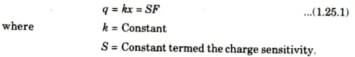
- 8. The net charge q on the surface is proportional to the amount x by which the charges have been displaced. The displacement is proportional to force. Therefore we can write,
b. Measurement of force using strain gauges and load cells. Discuss.
Ans. A. Measurement of force using strain gauge:
- 1. Strain gauge load cells are a particular kind of load cell that use an internal strain gauge assembly to translate the stress placed on them into electrical signals.
- 2. The voltage fluctuation brought on by the strain gauge’s deformation is utilised to measure the weight on the load cell.
- 3. A strain gauge translates variables like force, pressure, tension, weight, etc. into a change in resistance that can be measured afterwards. The resistance of a strain gauge varies with applied force.
- 4. Anytime an object is subjected to an external force, it has a tendency to change in size and shape, which affects its resistance.
- 5. An object’s internal resistance capability is measured by its strain, whereas its stress measures how much deformation it has undergone.
- 6. A metallic foil design is supported by an insulating flexible backing in any basic strain gauge.
- 7. An adhesive is used to secure the gauge to the stressed object. The foil is distorted by the object’s deformation, which ultimately alters the foil’s electrical resistance.
- 8. A Wheatstone bridge used to measure this change in resistivity has a gauge factor that connects it to strain.
- 9. The operation of a strain gauge relies on the relationship between electrical conductivity and the geometry of the conductor.
- 10. When a conductor is stretched over its elastic limit, it does not break; instead, it becomes longer and thinner.
- 11. It changes in length and width when squeezed, which eventually alters its resistance.
B. Measurement of force using load cell:
Load cell: A transducer is used in a load cell, a type of force gauge, to provide an electrical signal whose strength is directly proportionate to the force being measured.
Types:
- a. Pneumatic
- b. Hydraulic
- c. Strain gauge
- d. Piezoresistive
- e. Magnetostrictive.
Section 4: Hall Effect Sensor
a. What is the necessity of thermal imaging? Explain
Ans.
- 1. Thermal imaging is a technique for increasing object visibility in low-light conditions by detecting the item’s infrared radiation and building an image from that data.
- 2. The three most often utilised night vision technologies are low-light imaging, thermal imaging, and near-infrared lighting.
- 3. Environments with no ambient light can use thermal imaging Smoke, fog, and haze are among the obscurants that thermal imaging can penetrate.
b. Discuss the working principle and applications of Hall effect sensors. Can the output from the Hall effect sensor be in analog and digital form ? How ?
Ans. Working principle and applications of Hall effect sensors:
A. Hall Effect Sensor:
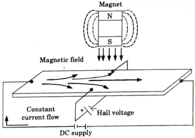
- 1. A Hall Effect sensor is a tool for gauging the strength of a magnetic field. The magnetic field intensity passing through it has a direct correlation with the output voltage.
- 2. A thin rectangular piece of p-type semiconductor material, such as Gallium Arsenide (GaAs), Indium Antimonide (InSb), or Indium Arsenide (InAs), that is conducting a steady current through itself is the basic building block of a hall effect sensor.
- 3. When the device is exposed to a magnetic field, the magnetic flux lines act as a force on the semiconductor material, deflecting the electrons and holes that carry charge to either side of the semiconductor slab.
- 4. The magnetic force that the charge carriers encounter as it passes through the semiconductor material is what causes them to move.
- 5. As these electrons and holes flow sideways, the accumulation of these charge carriers creates a potential difference between the two sides of the semiconductor material.
- 6. Next, the presence of an external magnetic field that is perpendicular to it has an impact on how electrons pass through semiconductor materials; this impact is stronger for materials with flat, rectangular shapes.
- 7. Fig. illustrates the Hall Effect sensor’s basic operation. The idea behind Hall Effect sensors is that when a beam of charged particles passes through a magnetic field, forces are exerted on the particles, causing the beam to be deflected from its intended path.
- 8. The disc will then have a negative charge on one side and a positive charge on the other.
- 9. This charge separation produces a potential difference, which is a measurement of the magnetic field’s separation from the current-carrying disc.
B. Hall effect sensor to measure the fluid level in a container:
- 1. The measuring of fluid level in a container is the typical application of a Hall Effect sensor.
- 2. The structure of the container is a float with a permanent magnet fastened to the top. The shell is mounted with an electrical circuit and a current-carrying disc.
- 3. The magnet will approach the disc as the fluid level rises, creating a potential difference. This voltage activates a valve that shuts off the flow of fluid into the container.
- 4. These sensors are used to determine an object’s position and quantify displacement. The appropriate signal conditioning circuitry is required for Hall Effect sensors.
- 5. They are capable of running at 100 kHz. They are very well-liked in industrial automation due to their non-contact nature of operation, excellent immunity to environmental contaminants, and capacity to withstand harsh conditions.
- Analog and digital hall effect sensors can be generally categorised into two groups. The output voltage of analogue sensors varies constantly, whereas the output voltage of digital sensors is either high or low.
Section 5: Sensing and Digitizing Function
a. Explore training the vision system in a pick and place robot.
Ans. VGR:
- 1. Vision Guided Robots (VGR) are robotic arms with built-in machine vision systems that are usually used in industrial pick-and-place applications.
- 2. The robot is guided to a desired position for pick and place by the machine vision system, which assists in locating an object.
VGR systems are typically used for high-volume, highly repeatable processes. Some of the more common applications include:
- 1. Loading/unloading parts from conveyors and feeding systems.
- 2. Loading/unloading nested parts from trays or boxes.
- 3. Part placement, assembly and packaging. Racking and de-racking.
- 5. Palletizing and de-palletizing.
- 6. Bin picking of random parts.
b. Sensing and digitizing function in machine vision. Give a detailed insight.
Ans. A. Sensing and digitizing image data:
- 1. To sense and digitise the images for watching, a camera is used. It will use unique lighting techniques to improve image contrast.
- 2. These pictures are converted to digital form, which is referred to as the vision data frame.
- 3. A frame grabber is integrated to constantly capture digital images at a speed of 30 frames per second. Every frame is split into a matrix rather than being projected as a scene.
- 4. The number of pixels in the image can be determined by conducting a sampling operation on it. The matrix’s components serve as a broad description of the pixels.
- 5. A pixel is shrunk to a number that can be used to gauge light intensity. Every pixel’s intensity is converted into a digital value as a consequence of this procedure, which is then stored in memory.
B. Image processing and analysis:
- 1. Data reduction and image interpretation procedures are carried out in this function.
- 2. To reduce the data, the threshold of an image frame is created as a binary image.
- 3. The frame will be transformed from raw picture data to feature value data with the aid of data reduction. Computer programming can be used to determine the feature value data.
- 4. To do this, the computer compares the picture descriptors, such as size and appearance, with previously saved information.
- 5. Regular machine vision system training will increase the efficiency of the picture processing and analysis function.
- 6. During the training procedure, various data are gathered, including perimeter length, outer and inner diameters, area, and more.
- 7. The camera will be very useful in this situation to determine whether the new items of feature value data and the computer models match.
Section 6: Signal Conditioning Equipment
a. What are the functions of signal conditioning equipment? Explain in detail.
Ans. A. Signal conversion:
- 1. A signal conditioner’s primary job is to capture the signal and transform it into a stronger electronic signal.
- 2. Industrial apps that use a variety of sensors to conduct measurements frequently use signal conversion.
- 3. Because of the various sensors being used, the signals produced might need to be transformed in order for the instruments to which they are attached to be able to use them.
B. Linearization:
- 1. When the signals generated by a sensor do not have a straight line connection with the physical measurement, certain signal conditioners can perform linearization.
- 2. This is the procedure for deciphering the software signal, which is typical for thermocouple readings.
- 3. Due to the fact that no sensor is entirely linear, this technique is used to achieve better accuracy.
C. Amplifying:
- 1. The process of boosting the information for processing or digitization comes first, and is known as signal amplification.
- 2. Signal amplification can be done in one of two ways: either by improving the incoming signal’s resolution or by raising the signal-to-noise ratio.
- 3. Signal conditioning uses a range of different amplifiers for different purposes:
- i. Instrumentation amplifiers: These exhibit high input impedance, high common mode rejection ratio (CMRR), and high gain and are designed for use with DC impulses.
- ii. Isolation amplifier: These are intended to transmit a small AC or differential signal while isolating high DC levels from the device.
D. Filtering:
- 1. Filtering, which involves reducing the signal frequency spectrum to only include legitimate data and exclude noise, is a crucial function of a signal conditioner.
- 2. Digital algorithms or inactive and active components can be used to create filters.
- 3. A passive filter only employs components with a maximum gain of one: capacitors, resistors, and inductors.
- 4. In addition to active components like operational amplifiers and transistors, an active filter also makes use of inactive components.
- 5. Modern signal conditioners use digital filters because they are simple to configure and don’t require any additional gear.
- 6. A digital filter is a mathematical filter that is applied to a signal to manipulate it, such as to pass or stop a specific frequency range.
- 7. They make use of logic devices like ASICs, FPGAs, or sequencing programmes with signal processors.
E. Evaluation and smart-functions:
- 1. Modern signal conditioners have additional functions for signal evaluation and measurement data pre-processing to offer additional advantages to the user and the process.
- 2. This makes it easier to quickly monitor and assess warnings and alarms immediately through an electrical switching output.
- 3. Additional smart functions, such as an internal calculated channel, can manage technological and mathematical processes, such as the addition of sensor signals.
- 4. These features assist in obtaining a quick-reacting system and lessen the burden on the machine management.
F. Interfaces:
- 1. Signal converters must send sensor data to the machine control using standardized interfaces and protocols.
- 2. Either analogue or digital connections are possible. Common analogue interfaces include voltage (+/- 10 V) or current (+/- 20 mA) signals, which are simple to manage but require distinct wiring for each signal.
- 3. Today’s digital interfaces (PROFINET, EtherCAT, EtherNet/lP) are Ethernet-based bus-interfaces that enable the connection of multiple components using a single cable.
- 4. This saves on wiring and enables the transmission of extra data, such as component diagnostic data, which is crucial for minimising downtime and accelerating maintenance.
b. Explain the elements of data acquisition systems and conversion.
Ans. A. Data acquisition (DAQ):
- 1. Data acquisition (DAQ) is the process of using a computer to measure a voltage, current, temperature, pressure, vibration, or sound-related electrical or physical event.
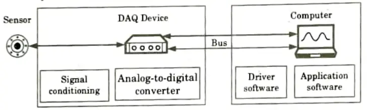
- 2. Sensors, DAQ measurement devices, and a computer running application software make up a DAQ system.
B. Components:
- 1. Sensor: An electrical signal that can be measured, such as voltage or resistance, is produced when a sensor, also known as a transducer, transforms a physical event, such as temperature or vibration.
- 2. DAQ device: By digitizing inbound analogue signals to make them readable by computers, a DAQ device serves as the interface between a computer and signals from the outside world. DAQ devices include three key components:
- a. Signal conditioning circuitry: Transforms noisy real-world signals into forms that can be measured efficiently and precisely.
- b. Analog-to-digital converters (ADCs): Digitize real-world analog data into digit.
- c. Computer bus: Enables the DAQ device to transmit data to a computer. Examples include USB, PCIe, or Ethernet.
- 3. Computer and software: To process, visualize, and store measurement data, a computer with DAQ software is needed. representations that can be manipulated by machines.
- a. Driver software: Allows application software to manage your DAQ device via menu-driven configuration or a programmable API.
- b. Application software: Provides a ready-made experience for acquiring, analyzing, and displaying data to the user. Menu-driven systems are used for configuration.
- c. Programming environment: Users can create their own application to acquire, analyze, and display data by utilizing function libraries (APIs) to access and control their DAQ device.
Section 7: Development of Smart City
a. What are smart sensors? Discuss in detail electric vehicles.
Ans. A. Smart sensor:
- 1. A smart sensor is merely an acronym for “Sensing, Monitoring, and Remote Transmission.”
- 2. It can be analogue or digital in nature, and it can be coupled with a processing device and a communication interface. These devices are capable of producing an electrical output.
- 3. When paired with appropriate interfacing devices, these sensors are referred to as intelligent sensors.
- 4. It can be defined as a microprocessor-based sensor which can perform one or more number of the functions like logical functions, decision making, two-way communication, etc. It can be simply expressed as,
Sensors + Suitable interfacing circuits = Smart sensors
- 5. Smart sensors vary from conventional sensors in that they have special functions such as ranging, calibration, communication with other devices, and so on.
B. Electric vehicle:
- 1. The concept of using electric motors to power vehicles arose after the invention of the motor itself.
- 2. Between 1897 and 1900, EVs accounted for 28% of total car sales and were preferred over internal combustion engine (ICE) vehicles.
- 3. However, the ICE types gained speed after that, and with extremely low oil prices, they quickly conquered the market.
- 4. However, current energy and environmental concerns have accelerated the creation of EVs.
- 5. In terms of the climate, EVs can provide zero-emission urban transportation.
- 6. In terms of energy, EVs can provide a safe, comprehensive, and balanced energy option, such as the use of different types of renewable energies.
- 7. There are additional causes to switch to EVs. They, for example, lower long-term transportation expenses. Superior efficiency and comfort can also be provided by electronic features.
b. Discuss the development of smart city using smart sensors.
Ans. A. Water management:
- 1. Currently, big cities waste up to 50% of their water due to pipe leaks. Water leaks can be easily discovered and corrected with sensors installed on each pipe.
- 2. In addition, to save water, irrigation systems in public parks can be set to turn off automatically when rain is sensed.
B. Energy management:
- 1. Sensors have also enabled the idea of “Advanced Metering Infrastructure (AMI),” which underpins urban energy management.
- 2. Cities are contemplating the use of “Smart metres,” which are equipped with Phase Measurement Unit (PMU) sensors and a communication module that allows for two-way communication between the consumer and the supplier.
- 3. It assists utility service providers in checking metre status previous to dispatching a repair team in response to a customer call.
- 4. These checks avoid unnecessary dispatch of field crews to customer locations.
- 5. For consumers, it can provide real-time energy consumption detail in an easy-to-understand format.
- 6. Using this data, users can alter their preferences and make more informed decisions about their usage without having to wait for their monthly energy bill.
C. Smart street lights:
- 1. Street lights in cities remain on even when there is no activity in the area.
- 2. It also becomes harder for authorities to detect any flaws or theft of street lighting.
- 3. With sensors, lights can go dim when they aren’t needed and authorities can get a text message practically instantaneously anytime there is a defect or tampering in street lights.
D. Waste management:
- 1. Municipalities can be notified when garbage bins are nearing capacity by installing sensors in them.
- 2. The Netherlands was the first country to produce “Intelligent Bins,” which send text messages to officials whenever the bins are full or damaged.
E. Transport management (smart parking):
- 1. Sensors that detect the nearest available parking space can help to reduce traffic.
- 2. Motorists receive timely information via text messages, allowing them to quickly locate a free parking space, saving time and fuel.
F. Real-time pollution management:
- 1. The ambient air quality (AAQ) of cities can be monitored by sensors mounted on poles.
- 2. Citizens can monitor the pollution concentration in each street of the city or they can get automatic alarms when the pollution level rises beyond a certain level.
6 thoughts on “Sensor and Transducers: Aktu Solved Question Paper Quantum Notes”