
Optical Network: AKTU Solved Question Paper offers comprehensive test preparation materials. These answers to the questions aid in conceptual comprehension, problem-solving exercise, and topic selection for the best exam preparation.
Dudes 🤔.. You want more useful details regarding this subject. Please keep in mind this as well.

Important Questions For Optical Network:
*Quantum          *B.tech-Syllabus
*Circulars           *B.tech AKTU RESULT
* Btech 4th Year
Section A: Short Question Optical Network
a. Define the single mode fiber.
Ans. Single mode fiber is an optical fiber designed to carry only a single mode of light-the transverse mode.
b. List the advantages for using optical fiber in long haul communication.
Ans. Advantages of optical fiber :
- 1. The optical fiber is light weight and more compact.
- 2. The external disturbance is well-protected by optical fiber.
- 3. It has higher bandwidth.
c. State the function of couplers.
Ans. The basic function of coupler is to transmit power, accommodate misalignment and compensate for axial movement.
d. Describe difference between SONET and ATM.
Ans.
| S. No. | SONET | ATM |
| 1. | SONET defines a method for transmitting digital data at high speeds over optical cabling. | ATM defines how to frame the traffic, how to address the traffic so that DTE devices can communicate. |
| 2. | SONET provides layer 1 features. | ATM provides layer 2 features over SONET. |
| 3. | SONET is physical structure. | ATM is a transmission protocol. |
e. What is photonic signal processing ?
Ans. Photonic signal processing allows for the realisation of exceptionally high multi gigahertz sampling frequencies, hence circumventing fundamental electronic limitations.
f. List out the name of switching methods used in optical network.
Ans.
- 1. Bulk mechanical switches.
- 2. Micro-Electro-Mechanical system switches.
- 3. Liquid crystal switches.
- 4. Electro-optic switches.
- 5. Thermo-optic switches.
g. Summarize the need of optical fiber in the communication.
Ans. Need of optical fiber in communication are :
- 1. For high bandwidth.
- 2. For long distance.
- 3. For immunity to electromagnetic interference.
h. Describe different capabilities of optical transport network.
Ans. Different capabilities of optical transport network are :
- 1. The Optical Transport Network (OTN) is a network-wide framework that adds SONET/SDH-like capabilities to WDM equipment.
- 2. The Optical Transport Network eliminates the difficulties associated with SONET/SDH overhead.
- 3. OTN’s improved multiplexing capability provides for a variety of traffic types such as ethernet, storage, digital video, and SONET/ SDH.
i. Discuss the bidirectional protection switching.
Ans.
- 1. If a single fibre is severed, both directions of transmission are shifted to the protection fibres.
- 2. If bidirectional switching is required, the receiver must notify the transmitter that a cut has occurred.
- 3. This requires a signaling protocol, called an automatic protection switching (APS) protocol.
j. Differentiate between broadcast and switched network.
Ans.
| S. No. | Broadcast Network | Switched Network |
| 1. | Information transmitted by any node is received by every other node in network. | Information is transmitted to a ub-set of designated nodes. |
| 2. | Examples: Usually in LANs (Ethernet, WaveLAN) | Examples: WANs (Telephony, Network, Internet) |
Section B: Medium Question of Optical Network
a. Describe how the attenuation affects the signal in fiber optic communication.
Ans. This can be occurred due to the following reasons :
- i. Transmission Medium: Once all of the messages have been sent down, an electromagnetic field can form surrounding the transmission, and energy losses will occur in the cable’s underside dependent on the length and frequency of the cable.
- ii. Crosstalk: Crosstalk from nearby cable can cause this within cables like conductive metal or copper.
- iii. Connectors and Conductors :
- 1. Attenuation can occur when a signal passes across dissimilar conductive standards and connéctor surfaces. The circuits can be dampened by employing repeaters for signal amplification.
- 2. When using copper conductors, the high-frequency signal and further attenuation can occur across the length of the cable. Because modern communications use HFs (high-frequency), mediums with smooth attenuation across all frequencies, such as fibre optics, are used instead of traditional copper connections.
- iv. Noise: Additional noise on networks such as radio frequencies, leakage in wires, electrical currents can interfere by the signal to cause this.
- v. Physical Environs: Physical environs which include installation of improper wiring, wall barriers, the temperature can alter the transmission, then attenuation can be caused.
- vi. Travel Distance: When transmission in a cable travels over long distances, such as from source (present location) to destination (connection supplier), it encounters greater noise.
b. Differentiate between circulator and isolator.
Ans.
| S. No. | Circulator | Isolator |
| 1. | It has multiple ports typically 3 or 4. | It is two port device. |
| 2. | Circulators are used to construct optical add/drop multiplexer. | Isolators are used in optical amplifier and laser to prevent reflections. |
| 3. | It is used as isolator by terminating one port. | It cannot be used as circulator. |
| 4. | Each terminal is connected only to the next terminal. | If input is given in port 1, output is obtained at port 2 and vice-versa. |
c. Appraise the key attributes for SONET/SDH in comparison of PDH.
Ans.
- 1. SONET (Synchronous Optical Network) is the current high-speed signal transmission and multiplexing standard in North America’s carrier infrastructure.
- 2. SDH (Synchronous Digital Hierarchy), a closely related standard, has been used in Europe and Japan, as well as for the majority of underwater links.
- 3. PDH (Plesiochronous Digital Hierarchy) had various issues, which prompted carriers and vendors to seek a new transmission and multiplexing standard known as SONET/SDH standards, which eliminated many PDH-related issues.
Advantages of SONET/SDH :
a. Multiplexing simplification :
- 1. SONET/synchronous SDH’s multiplexing topology significantly reduces the cost of multiplexing and demultiplexing.
- 2. By locating the relevant places of the corresponding bits in the multiplexed signal, a lower-speed signal can be retrieved from a multiplexed SONET/SDH stream in a single step.
- 3. SONET multiplexers and demultiplexers are much easier to construct than their asynchronous counterparts.
b. Management :
- 1. The SONET and SDH standards include significant network management information, such as thorough performance monitoring, identification of connectivity and traffic type, failure detection and reporting, and a data communication channel for conveying management information between nodes.
c. Interoperability :
- 1. SONET and SDH eliminate interoperability issues by creating standard optical interfaces that allow interoperability on the link between equipment from different vendors.
d. Network availability :
- 1. The SONET and SDH standards have grown to include specific network topologies, protection mechanisms, and associated protocols in order to provide high-availability services.
- 2. The service restoration time following a breakdown in a SONET or SDH network is substantially shorter (less than 60 ms) than in a PDH network, which normally takes several seconds to minutes.
d. Describe why optical layer protection needed.
Ans. Reason :
- 1. The optical layer offers light channels for SONET, IP, and 10-Gigabit Ethernet client layers.
- 2. The optical layer is more efficient than the client layer in handling some defects.
- 3. Optical layer protection can be utilised to provide additional network resilience, such as protection against multiple failures.
- 4. The optical layer protection utilised to improve SONET security. SONET security is now dependent on rings (UPSR/ BLSR).
- 5. The optical layer protects traffic in units of light paths.
e. Explain, how the bit interleaved multiplexing operation performed, optically.
Ans. Bit interleaving :
- 1. This operation is illustrated in Fig. The periodic pulse train generated by a mode-locked laser is split, and one copy is created for each data stream to be multiplexed.
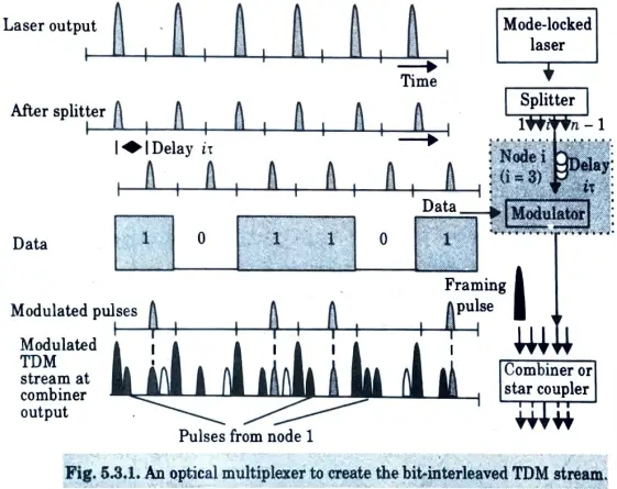
- 2. The pulse train for the ith data stream, i = 1, 2,…n is delayed by i 𝛕.
- 3. This delay can be achieved by passing the pulse train through the appropriate length of optical fiber.
- 4. The velocity of light in silica fiber is about 2 x 10⁸ m/s, 1 meter of fiber provides a delay of about 5 ns. Thus the delayed pulse streams are non-overlapping in time.
- 5. The undelayed pulse stream is used for the framing pulses.
- 6. Each data stream is used to externally modulate the appropriately delayed periodic pulse stream.
- 7. The outputs of the external modulator and the framing pulse stream are combined to obtain the bit-interleaved optical TDM stream.
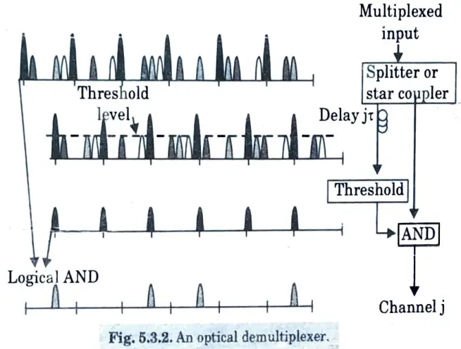
- 8. The corresponding demultiplexing operation is illustrated in Fig.
Section 3: Essential Questions in Optical Network
a. Illustrate the building blocks of optical network.
Ans. 1. There are two generations of optical networks :
a. First generation
b. Second generation
a. First generation :
- 1. In the first generation, optics were primarily used for transmission and capacity.
- 2. Compared to copper lines, optical fibre provides reduced bit error rates and higher capacities.
- 3. Electronics handled all switching and other sophisticated network activities.
- 4. In first-generation networks, a node’s electronics must handle not only all data intended for that node, but also all data sent through that node to other nodes in the network.
- 5. Examples of first-generation optical networks are SONET (synchronous optical network) and the essentially similar SDH (synchronous digital hierarchy) network.
b. Second generation :
- 1. The optical layer of second generation optical networks contains routing, switching, and intelligence.
- 2. In second generation, data passing from one node to another might be routed in the optical domain, reducing the burden on the underlying electronics at the node significantly. This is a major motivator for second generation optical networks.
Optical networks :
- 1. The architecture of optical network is shown in Fig. We call this network a wavelength-routing network.
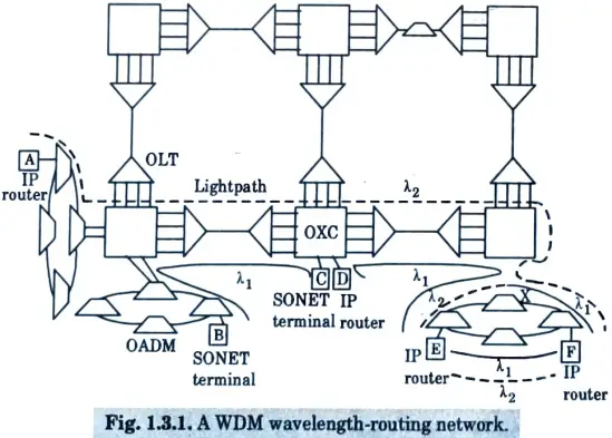
2. The network provides lightpaths to its users, such as SONET terminals or IP routers.
3. Lightpaths are end-to-end optical connections carried over a wavelength on each intermediate link from a source node to a destination node.
4. Lightpaths are routed and switched from one link to another at intermediate nodes in the network.
5. In a wavelength-routing network, different lightpaths can use the same wavelength as long as they do not have any common links. This permits the same wavelength to be utilised geographically across the network.
6. Optical line terminals (OLTs), optical add/drop multiplexers (OADM), and optical cross connects are fundamental network devices that enable optical networking (OXCs).
b. Explain different parts of public networks.
Ans.
- 1. Fig. 1 shows an overview of a typical public fiber network architecture.
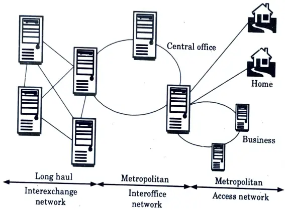
- 2. The network is enormous and complex, with different carriers owning and operating different sections of it.
- 3. The network’s nodes are central offices, often known as points of presence (POPs).
- 4. The connections between nodes are made up of fibre pairs, and in many cases, many fibre pairs.
- 5. Long-distance network links are notoriously expensive to build.
- As a result, the long-distance network topology is fairly sparse.
- 7. In Europe, link lengths are shorter and long-distance network topologies are denser.
- 8. At the same time, it is critical to provide alternate traffic routes in the event that part of the links fail.
- 9. As a result of these constraints, ring topologies have become widely used.
- 10. Rings are scarce (just two links per node), but they nonetheless provide an additional path for traffic rerouting.
- 11. A meshed network is frequently constructed in the form of interconnected ring networks.
Section 4: Overview Questions in Optical Network
a. Elaborate Bragg grating with diagram.
Ans.
- 1. A Bragg grating is any periodic disruption in the propagating medium.
- 2. This perturbation is typically a periodic fluctuation in the medium’s refractive index.
- 3. Fiber-written Bragg gratings can be utilised to create a number of devices such as filters, add/drop multiplexers, and dispersion compensators.
Principle of Operation :
- 1. Consider two waves propagating in opposite directions with propagation constants β0 and β1.
- 2. Energy is coupled from one wave to the other if they satisfy the Bragg phase-matching condition :
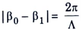
where, Λ is the period of the grating.
3. In a Bragg grating, energy from the forward propagating mode of a wave at the right wavelength is coupled into a backward propagating mode.
4. Consider a light wave with propagation constant B propagating from left to right.
5. The energy from this wave is coupled onto a scattered wave travelling in the opposite direction at the same wavelength provided
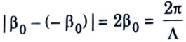
6. Letting β0 = 2𝜋 neff/𝛌0, 𝛌0 being the wavelength of the incident wave and ηeff the effective refractive index of the waveguide or fiber, the wave is reflected provided
𝛌0 = 2neffΛ.
This wavelength 𝛌0 is called the Bragg wavelength.
7. The operation of the Bragg grating can be understood with reference to Fig.which shows a periodic variation in refractive index.
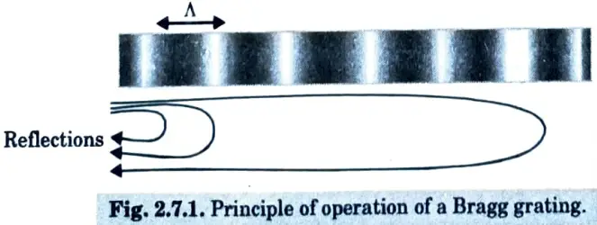
8. The incident wave is reflected from each period of the grating.
9. These reflections add in phase when the path length in wavelength 𝛌0 in each period is equal to half the incident wavelength 𝛌0.
10. This is equivalent to neff Λ = 𝛌0/2, which is the Bragg condition.
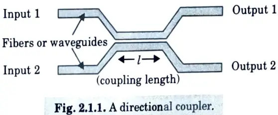
b. Discuss the design of a directional coupler.
Ans.
- 1. A directional coupler is used to combine and split signals in an optical network. A 2 x 2 coupler consists of two input ports and two output ports, is shown in Fig.
- 2. The most commonly used couplers are made by fusing two fibers together in the middle and are called as fused fiber couplers. Couplers can also be fabricated using waveguides in integrated optics.
- 3. A 2 x 2 coupler, shown in Fig., takes a fraction a of the power from input 1 and places it on output l and the remaining fraction 1-α on output 2.
- 4. Similarly, a fraction 1-α of the power from input 2 is distributed to output 1 and the remaining power to output 2 where a is the coupling ratio.
- 5. Across a large range, the coupler can be constructed to be either wavelength selective or wavelength independent (also known as wavelength flat).
- 6. With a wavelength-independent device, an is independent of wavelength, whereas in a wavelength.h selective device, an is wavelength dependent.
- 7. A coupler is a versatile device that can be used in a variety of optical networks. The most basic application is to merge or separate network signals.
Section 5: Important Question in Optical Network
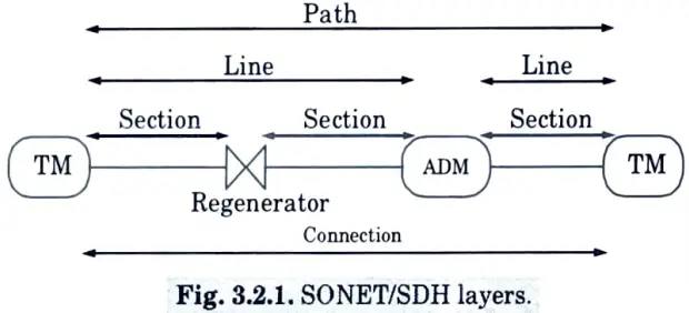
a. Describe path, line, section and physical layers in SONET layer.
Ans.
- 1. The SONET layer consists of four sublayers-path, line, section, and physical layers.
- 2. Fig. shows the top three layers.
- 3. Except for the physical layer, each layer has a set of overhead bytes that are utilised for a variety of functions.
- 4. In a network element, these overhead bytes are added when the layer is created and removed when the layer is terminated.
- 5. In SONET (and SDH), the path layer is in charge of end-to-end connections between nodes and is terminated only at the ends of a SONET connection.
- 6. While intermediary nodes may undertake performance monitoring on the path layer signals, the path overhead is inserted at the source node and terminated at the destination node.
- 7. Each connection traverses a set of links and intermediate nodes in the network.
- 8. In SDH, the line layer (multiplex section layer) multiplexes several path-layer connections onto a single link between two nodes.
- 9. As a result, the line layer is terminated at each intermediate line terminal multiplexer (TM) or add/drop multiplexer (ADM) along a SONET connection’s path.
- 10. In the event of a line failure, the line layer is also responsible for conducting certain types of protection switching to restore service.
- 11. Each link is made up of several pieces that match to link segments between regenerators.
- 12. Each regenerator in the network terminates the section layer (regenerator-section layer in SDH).
- 13. Finally, the physical layer is responsible for actual transmission of bits across the fiber.
b. Explain the parameters used to characterize the suitability of a switch for optical networking applications.
Ans. In addition to the switching time and the number of ports, the other important parameters used to characterize the suitability of a switch for optical networking applications are the following :
- 1. An on-off switch’s extinction ratio is the ratio of the output power in the on state to the output power in the off state. This ratio should be as high as feasible, and it is especially critical in external modulators.
- 2. A switch’s insertion loss is the fraction of power (typically represented in decibels) lost due to the presence of the switch, and it must be as tiny as feasible.
- 3. Switches are not ideal. Even if input x is nominally connected to output y, some power from input x may appear at the other outputs. For a given switching state or interconnection pattern and output, the crosstalk is the ratio of the power at that output from the desired input to the power from all other inputs. Usually, the crosstalk of a switch is defined as the worst case crosstalk over all outputs and interconnection patterns.
- 4. Switches, like other components, should have a minimal polarisation dependent loss (PDL).
- 5. A latching switch retains its switch state even when the power to the switch is switched off. This is a relatively desirable characteristic since it allows traffic to pass through the switch even when the power goes off.
- 6. The switch must have a reading capability to monitor its current status.
- 7. Switch reliability is an essential consideration in telecommunications applications.
Section 6: Long Explained Questions in Optical Network
a. Explain the terms enhanced HFC and FTC.
Ans. A. Enhanced HFC :
- 1. While the word HFC is commonly used to describe existing cable infrastructure, it is also used to represent an upgraded version of this architecture known as an enhanced HFC architecture.
- 2. Because both the fibre and coax cable carry numerous subcarrier modulated streams and it is a broadcast network, the HFC design is better described as a subcarrier modulated fibre coax bus (SMFCB).
- 3. The network is being improved utilising a combination of strategies in order to give more bandwidth per user.
- 4. First, the transmission frequency range can be expanded from 500 MHz in current HFC systems to 1 GHz.
- 5. Enhanced HFC systems deployed in larger metropolitan areas can deliver up to 862 MHz of bandwidth.
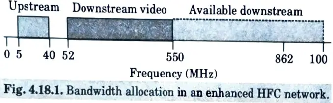
- 6. Using a passive optical star coupler, downstream data is transmitted from the head end to remote (fibre) nodes in a conventional enhanced HFC design, similar to the present cable network.
- 7. In recent deployments, high-power 1.55 m transmitters are sometimes used in conjunction with booster amplifiers to obtain a high split ratio.
- 8. Many coax trees branch out from a remote node to the network interface modules.
- 9. Analog subcarrier channels would be used to send downstream broadcast video to the house.
- 10. Video signals could be delivered as analogue AM-VSB streams that are compatible with existing home equipment.
- 11. Digital video, telecommunication, and data services can all be delivered over the same infrastructure.
- 12. Fig. shows the bandwidth usage in an enhanced HFC network.
B. FTTC :
- 1. In fiber to the curb (FTTC), data is transmitted digitally over optical fiber from the hub, or central office, to fiber-terminating nodes called optical network units (ONUs).
- 2. The expectation is that the fiber would get much closer to the subscriber with this architecture.
- 3. Depending on how close the fiber gets to an individual subscriber, different terms are employed to describe this architecture as shown in Fig.
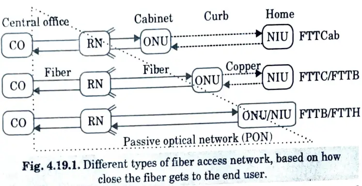
- 4. In the best-case scenario, fibre would be sent to each home; this architecture is known as fibre to the home (FTTH), and ONUs would replace NIUs.
- 5. In the event where ONU serves a small number of residences or buildings, say 8-64, this is referred to as FTTC or fibre to the building (FTTB).
- 6. FTTC typically places the fibre within 100 m of the end customer. In this situation, an extra distribution network connects the ONUS to the NIUs.
- 7. With the fibre to the cabinet (FTTCab) technique, the fibre is terminated in a nearby cabinet within roughly 1 km of the end user.
- 8. To ensure the viability of the FTTC architecture, the network from the CO to the ONU is often a passive optical network (PON).
- 9. The distant node is a simple passive device, such as an optical star coupler, that is sometimes housed in the central office rather than in the field.
- 10. The term FTTC is most commonly used to refer to a version in which signals are transmitted from the central office to the ONUs and the ONUs share a common total bandwidth in a time division multiplexed method.
- 11. In the context of FTTC, the feeder network is the network segment between the central office and the remote node, while the distribution network is the network segment between the remote node and the ONUs.
- 12. The FTTC architecture is sometimes also called baseband modulated fiber coax bus (BMFCB) or switched digital video (SDV).
b. Describe the difference among protection at different layers.
Ans. 1. There are two fundamental types of protection mechanisms used in point-to-point links :
a. 1 + 1 protection and
b. 1 : 1 or, more generally, 1 : N protection, as shown in Fig.
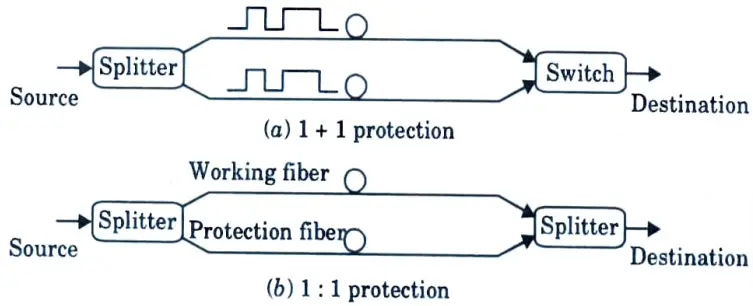
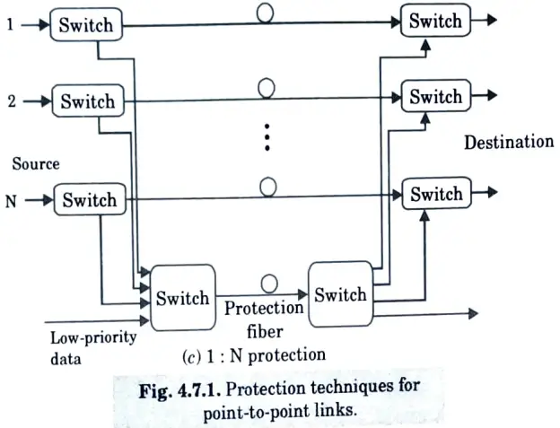
2. Both operate in the line or multiplex section layer.
a. 1 + 1 Protection :
- 1. In 1 + 1 protection, traffic is transmitted simultaneously on two separate fibers (usually over disjoint routes) from the source to the destination.
- 2. Assuming unidirectional protection switching, the destination simply selects one of the two fibers for reception.
- 3. If that fiber is cut, the destination simply switches over to the other fiber and continues to receive data.
- 4. This form of protection is very fast and requires no signaling protocol between the two ends.
b. 1 : 1 Protection :
- 1. In 1:1 protection, there are still two fibers from the source to the destination.
- 2. If working fiber is cut, the source and destination both switch over to the other protection fiber.
- 3. An APS protocol is required for signaling between the source and destination.
- 4. As a result of the additional communication overhead, 1:1 protection does not restore traffic as quickly as unidirectional 1+1 protection.
- 5. It has two significant advantages over 1+1 protection.
- The first is that the protective fibre is unused during regular operation. As a result, it can be used to send lower-priority traffic.
- 7. Another advantage is that the 1:1 protection can be extended such that a single protection fibre can be shared by multiple working strands.
- 8. In a more general 1:N protection scheme, N working fibers share a single protection fiber.
- 9. 1:N protection arrangement can handle the failure of any single working fiber.
Section 7: Briefly Question in Optical Network
a. Explain the difference between bit interleaved and packet interleaved optical time division multiplexing.
Ans.
| S. No. | Bit-interleaved | Packet interleaved |
| 1. | The interleaving is done on a bit-by-bit basis. | The interleaving is done on a packet-by packet basis. |
| 2. | In the bit-interleaved case, if n input data streams are to be multiplexed, a framing pulse is used every n bits | In packet-interleaved case, framing pulses mark the boundary between packets. |
| 3. | In the case of bit interleaving, modulated data stream has narrow pulses. | In the case of packet interleaving, modulated data stream do not have narrow pulses. |
b. Write short note on SONET/SDH.
Ans.
- 1. SONET (Synchronous Optical Network) is the current high-speed signal transmission and multiplexing standard in North America’s carrier infrastructure.
- 2. SDH (Synchronous Digital Hierarchy), a closely related standard, has been used in Europe and Japan, as well as for the majority of underwater links.
- 3. PDH (Plesiochronous Digital Hierarchy) had various issues, which prompted carriers and vendors to seek a new transmission and multiplexing standard known as SONET/SDH standards, which eliminated many PDH-related issues.
Advantages of SONET/SDH :
a. Multiplexing simplification :
- 1. SONET/synchronous SDH’s multiplexing topology significantly reduces the cost of multiplexing and demultiplexing.
- 2. By locating the relevant places of the corresponding bits in the multiplexed signal, a lower-speed signal can be retrieved from a multiplexed SONET/SDH stream in a single step.
- 3. SONET multiplexers and demultiplexers are much easier to construct than their asynchronous counterparts.
b. Management :
- 1. The SONET and SDH standards include significant network management information, such as thorough performance monitoring, identification of connectivity and traffic type, failure detection and reporting, and a data communication channel for conveying management information between nodes.
c. Interoperability :
- 1. SONET and SDH avoid interoperability problem by defining standard optical interfaces that enable interoperability between equipment from different vendors on the link.
d. Network availability :
- 1. The SONET and SDH standards have grown to include specific network topologies, protection mechanisms, and associated protocols in order to provide high-availability services.
- 2. The service restoration time following a breakdown in a SONET or SDH network is substantially shorter (less than 60 ms) than in a PDH network, which normally takes several seconds to minutes.
1 thought on “Optical Network: AKTU Solved Question Paper”