HVAC Systems: AKTU question paper with answers provides B.Tech students with important practise material for HVAC Systems examinations by giving a comprehensive set of exam-oriented questions and extensive solutions.
Dudes 🤔.. You want more useful details regarding this subject. Please keep in mind this as well.

Important Questions For HVAC Systems:
*Quantum          *B.tech-Syllabus
*Circulars           *B.tech AKTU RESULT
* Btech 4th Year
Section A: Short Question HVAC Systems
a. What are future refrigerants ?
Ans.
- 1. HFOs are unsaturated organic compounds made up of hydrogen, fluorine, and carbon.
- 2. These organofluorine compounds have the potential to be used as refrigerants. Unlike traditional saturated hydrofluorocarbons (HFCs) and chlorofluorocarbons (CFCs), HFOs are olefins, also known as alkenes.
b. What do you understand by greenhouse effect ?
Ans. The greenhouse effect occurs when energy from the sun passes through a planet’s atmosphere and warms its surface, but the atmosphere prevents the heat from returning directly to space, resulting in a warmer planet.
c. Explain the importance of alignment circle pn psychrometric chart.
Ans. On the psychrometric chart, the alignment circle serves as a reference point. It is usually between 24°C and 26°C DBT and 50% – 60% RH. To plot various air conditioning processes, the alignment circle must be used in conjunction with the sensible heat factor.
d. Explain ADP.
Ans. ADP: The temperature at which the room sensible heat factor line intersects the saturation curve in a cooling with dehumidification process is known as the apparatus dew point (ADP).
e. What is performance index of a heat pump ? How is it related to COP of a refrigerator ?
Ans.
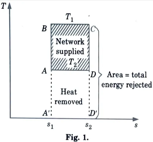
- 1. Fig. 1 shows the reversed Carnot cycle of heat pump.
- 2. The performance index of heat pump is the ratio of the energy delivered (the heating effect or total energy rejected) to the net work supplied as the COP.
- 3. Therefore we have

f. Differentiate between natural ventilation and mechanical ventilation.
Ans.
| S. No. | Natural Ventilation | Mechanical Ventilation |
| 1. | Natural ventilation is achieved by placing shafts at appropriate intervals along the tunnel alignment. | Mechanical ventilation is provided by one or more electric fans or blowers. |
| 2. | Natural ventilation is an economical method. | This method is costlier as they required to install numerous fans or blowers. |
g. Explain evaporative cooling.
Ans. Heat is neither added to nor removed from the water outside the air washer during the evaporative cooling process. A pump simply circulates the water.
h. What is soil air temperature?
Ans. The soil air temperature is defined as the outside air temperature that, in the absence of solar radiation, would produce the same temperature distribution and rate of heat transfer through a wall (or roof) as the combined effects of the actual outdoor temperature distribution and incident solar radiation.
i. Explain the role of duct in air-conditioning-systems.
Ans. Ducts are passages or conduits used in heating and ventilation. Ducts are installed when the conditioned air cannot be supplied directly from the air conditioning equipment to the spaces to be conditioned.
j. Suggest materials used in fabrication of ducts.
Ans. Materials used for ducts are as follows :
1. Galvanized Steel
2. Aluminium
3. Stainless Steel
4. Carbon Steel (Black Iron)
5. Copper
Section B : Btech Important Questions in HVAC System
a. A refrigerator working on an ideal vapor compression cycle uses refrigerant R-12. The minimum and maximum pressures of the cycle are 0.15 MPa and 0.9 MPa respectively. If the mass flow rate of the refrigerant is 0.045 kg/s, determine :
i. The rate of heat removal from the refrigerated space,
ii. Power input to the compressor,
iii. The rate of heat rejection to the environment, and
iv. COP of the system.
Ans. 1. T-s diagram of refrigeration cycle is shown in Fig. 2.
2. From refrigerant table, enthalpies of refrigerant at all four states are :
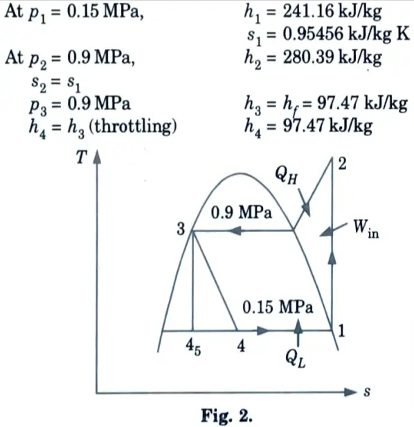
3. Rate of heat removal from refrigerated space,
QL = m(h1 – h4) = 0.045(241.16 97.47) = 6.466 kJ/kg
4. Power input to compressor,
Win = m(h2 – h1) = 0.045(280.39 -241.16)
= 1.765 kJ/sec
5. Rate of heat rejection,
QH m(h2 – h3) = 0.045(280.3997.47) = 8.23 kJ/sec
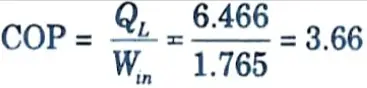
6. COP of refrigerator,
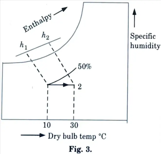
b. The moist air at 10 °C and 50 % relative humidity enters a steam heating coil at the rate of 50 kg/s and the temperature at the exit is noted to be 30 °C. Determine :
i. Sensible heat transfer
ii. Mass flow rate of steam if it enters saturated at 100 °C and the condensate leaves at 65 °C.
Ans. Given: Td1 = 10 °C, ɸ1 = 50 %, Td2 = 30 °C, ma = 50 kg/sec, Ts = 100 °C, Tc = 65 °C
1. From psychrometric chart, enthalpy at point 1,
h1 = 19.3 kJ/kg of dry air
2. Enthalpy at point 2,
h2 = 39.8 kJ/kg of dry air
3. Sensible heat transfer,
Q = ma (h2 – h1)
= 50 (39.8 – 19.3)
= 1025 kJ/sec
4. From steam tables at 100 °C,
hg = 2676 kJ/kg
and enthalpy of condensate at 65 °C,
hf = 314.9 kJ/kg
5. Steam mass flow rate
= 0.4341 x 3600
= 1562.76 kg/h
c. Differentiate among all water, all air and air water air conditioning systems.
Ans.
| All Water System | All Air System | Air Water System |
| The fluid used in the thermal distribution system is water in all water systems. | In all air system, air is used as the media that transports energy. | Both air and water are used in an air water system to provide the necessary conditions. |
| Very less space is required. | More space is required. | Normal space is required. |
| These are appropriate for buildings that require individual room control, such as hotels. | These are appropriate for buildings with multiple zones that require individual control, such as office buildings. | These systems are used on the outside of buildings with high sensible loads. |
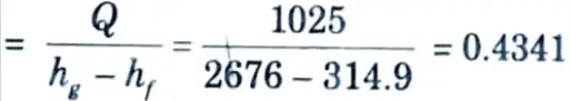
d. With neat sketch, explain how centralized air-conditioning systems differ from unitary air-conditioning system.
Ans. A. Centralized Air Conditioning System Sketch :
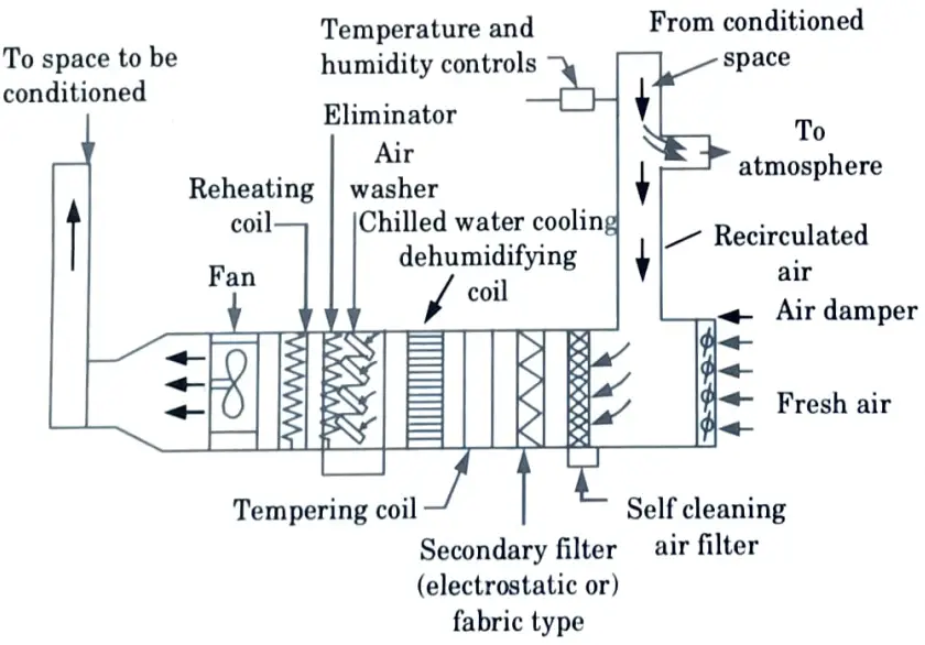
B. Unitary Air Conditioning System Sketch :
C. Difference :
| Characteristic | Centralized Air-conditioning System | Unitary Air-conditioning System |
| Configuration | A central system is custom-designed for a building and is classified by field assembly of the following components: source components, distribution system, and terminal elements. | A unitary system is essentially off-the-shelf, factory-assembled equipment that combines cooling/heating, distribution, delivery, and control functions into a single package. |
| Types | There are two types of |central air conditioning systems : Direct Expansion (DX) type and Chilled Water (CHW) type. | Unitary systems are essentially Direct Expansion (DX) type. |
| Heat Rejection Options | Central air conditioning systems expel heat by air or water cooling. | Most unitary systems use air cooled condensers to expel heat |
| Usage Patterns | Centralized systems are preferred where the usage time is high and consistent. | Where air conditioning requirements are low or intermittent, unitary systems are preferred. |
| Zoning | Central air conditioning systems may serve multiple thermal zones. | Unitary systems are only suitable for single thermal zone application. |
| Applications | When large buildings must be completely air conditioned, central systems are used. | Unitary systems are more appropriate for low to mid-rise buildings. |
e. Classify the ducts on the basis of its application, pressure inside it and the velocity of air in the duct.
Ans. Classification of Ducts: The ducts may be classified as follows :
- 1. Supply Air Duct: The supply air duct is the duct that transports conditioned air from the air conditioning equipment to the space to be conditioned.
- 2. Return Air Duct: The return air duct transports recirculating air from the conditioned space back to the air conditioning equipment.
- 3. Fresh Air Duct: The duct which carries the outside air is called fresh air duct.
- 4. Low Pressure Duct: A duct is said to be low pressure if the static pressure in it is less than 50 mm of water gauge.
- 5. Medium Pressure Duct: When the static pressure in the duct exceeds 150 mm of water gauge, the duct is considered medium pressure.
- 6. High Pressure Duct: When the static pressure in the duct is from 150 to 250 mm of water gauge, the duct is said to be a high pressure duct.
- 7. Low Velocity Duct: When the velocity of air in the duct is upto 600 m/min, the duct is said to be a low velocity duct.
Section 3 : Refrigeration System in HVAC System
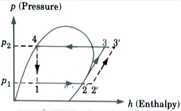
a. Explain the effects of superheating, sub cooling and reduction in condenser pressure on the COP of the vapor compression refrigeration system.
Ans. A. Effects of Superheating :
- 1. It may be seen from the Fig. the effect of superheating process (2-2’) is to increase the refrigerating effect from (h2 – h1) to (h2’ – h1) but this increase in refrigerating effect is at the cost of increase in amount of work (h3 – h2) to (h3 – h2’) spent to attain the upper pressure limit.
- 2. Since the increase in work is more as compared to increase in refrigerating effect, therefore overall effect of the superheating is to give a low value of COP.
Effect of Sub Cooling of Condensate :
1. From p-h diagram, Fig. it is clear that refrigerating effect, RE increases from (h2 – h1) to (h2 – h1’) without any change in compressor work, WC.
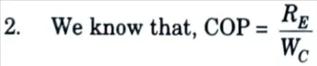
- 3. The sub cooling results in increase of COP provided that no further energy has to be spent to obtain the extra cold coolant required.
- 4. Sub cooling of condensate is generally used to improve the COP of the cycle.
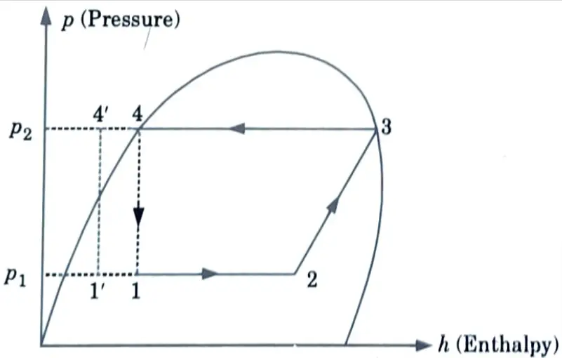
B. Effects of Reduction in condenser pressure :
- 1. In actual practice, the discharge pressure (or condenser pressure) increases due to frictional resistance of flow of the refrigerant.
- 2. Let us consider a theoretical vapour compression cycle 1-2’-3’-4′ when the discharge pressure increases from pd to pd’ as shown on p-h diagram in Fig.
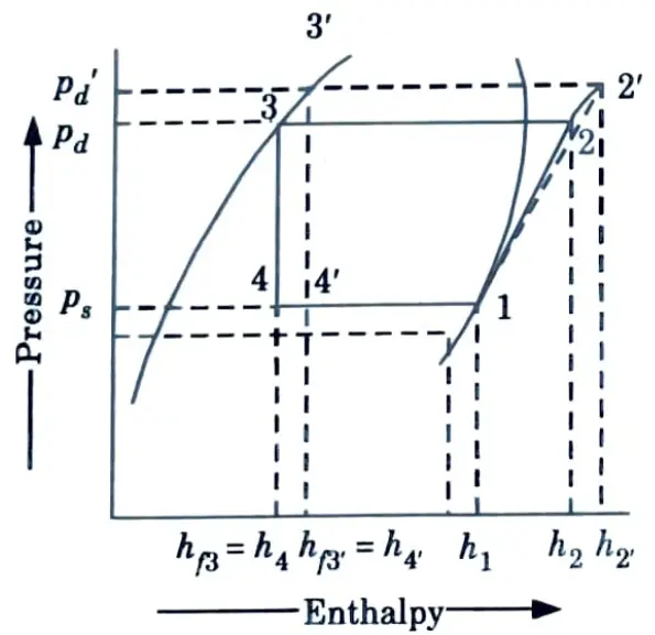
- 3. It may be noted that the increase in discharge pressure:
- i. Decreases the refrigerating effect from (h1 – h4) to (h1 – h4’), and
- ii. Increases the work required for compression from (h2 – h1) to (h2’ -h1).
- 4. From above, we see that the effect of increase in discharge pressure is similar to the effect of decrease in suction pressure.
b. Explain classification of refrigerants in detail.
Ans. Refrigerants can be classified as primary refrigerants and secondary refrigerants. These are discussed as given below :
a. Primary Refrigerants: Primary refrigerants are those that directly participate in the refrigeration system and cool the substance by absorbing latent heat.
Example: Ammonia, Caron dioxide, Sulphur dioxide, Methyl chloride, Freon group etc.
Types of Primary Refrigerants :
i. Halocarbon Compounds: They are formed by replacing one or more hydrogen atoms in ethane or methane with halogens (chlorine, bromine or fluorine).
Example: R-11 (Trichloro-nono fluoromethane), R-12 (Dichlorodi fluoromethane)
ii. Azeotropes: This group of refrigerants is made up of mixtures of various substances. Distillation cannot separate these substances into their constituents. They have fixed thermodynamic properties and do not separate as temperature and pressure change. An azeotrope behaves similarly to a simple substance.
Example: R-500, R-502, etc.
iii. Hydrocarbons: The majority of the refrigerants in this category are organic compounds. Several hydrocarbons are successfully used in commercial and industrial settings. The majority of them have acceptable thermodynamic properties but are highly flammable.
Example: Methane, Ethane Butane, etc.
iv. Inorganic Refrigerants: Prior to the introduction of halo-carbon refrigerants, only inorganic refrigerants were used. Because of their inherent thermodynamic and physical properties, these refrigerants are still in use.
Example: R-717 (Ammonia), R-729 (Air), etc.
v. Unsaturated Organic Compounds: The refrigerants belonging to this group possess ethylene or propylene as their constituents.
Example: R-1120 (Trichloroethylene), R-1130 (Dichloroethylene), etc.
b. Secondary Refrigerants :
- 1. Secondary refrigerants are refrigerants that are first cooled with the help of primary refrigerants before being used for cooling.
- 2. These refrigerants cool substances by absorbing sensible heat from them.
- 3. Due to safety concerns, several applications prohibit the direct use of a refrigerant.
- 4. Toxic refrigerants, for example, cannot be used in residential building air conditioning.
- 5. Similarly, the amount of refrigerant required for circulation in a large cold storage would be so large that the cost would be comparable to that of refrigeration systems.
- 6. In such cases, the cheaper grade suitable cooling media, such as water, brine solution of sodium chloride or calcium chloride, and so on, is chosen for indirect cooling.
Section 4 : Human Comfort in HVAC System
a. 400 m3/min of air at 20 °C DBT coming out from air conditioned hall is mixed with 150 m3/min of fresh air at 35 °C DBT and 45% RH adiabatically. Determine;
i. Enthalpy
ii. Specific humidity
iii. Specific volume and
iv. DPT of the mixture
Ans. Given: V2 = 400m3/min, tdb2 = 20 °C, tdp2 = 10 °C, V1 = 150 m3/min, tdb1 = 35 °C, ɸ1 = 45%
1. Locate point 1 at the intersection of 35°C DBT and 45 % RH lines.
2. Locate point 2 at the intersection of 20 °C DBT and 10 °C DPT lines.
3. From psychrometric chart, we find :
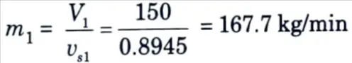
vs1 = 0.8945 m3/kg of dry air
h1 = 76.1 kJ/kg of dry air
W1 = 0.0158 kg/kg of dry air
vs2 = 0.8414 m3/kg of dry air
h2 = 39.1 kJ/kg of dry air
W2 = 0.0076 kJ/kg of dry air

4. Mass of fresh air at point 1,
5. Mass of air recirculated at point 2,
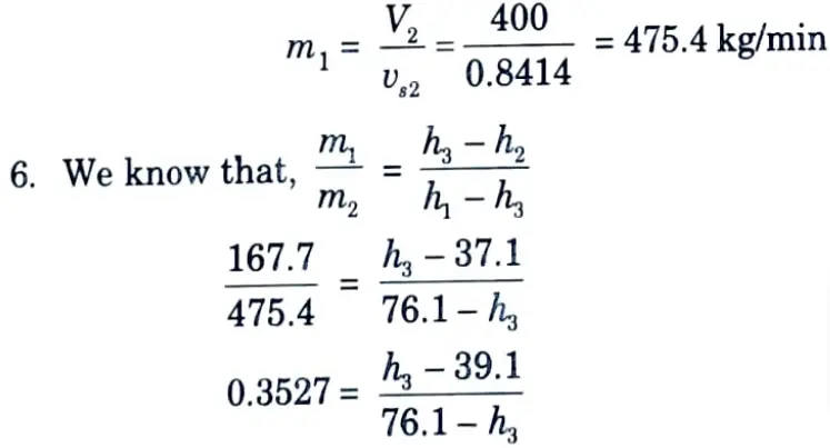
0.3527 (76.1 h3) = h3 – 39.1, 26.84 -0.3527 h3 = h3 – 39.1

7. Locate point 3 on the line joining 1 and 2 corresponding to enthalpy
h3 = 48.75 kJ/kg of dry air, as shown in Fig. 4.
8. From psychrometric chart, corresponding to point 3, we have
Specific volume, vs3 = 0.8543 m3/kg of dry air
Humidity ratio, W3 = 0.0097 kJ/kg of dry air Dew point temperature, tdp3 = 13.7 °C
b. Define human comfort. Explain the factors affecting human comfort.
Ans. A. Human Comfort: Human comfort is the mental state that expresses satisfaction with the thermal environment. Thermal comfort is the subjective perception of temperature in a given environment.
B. Factors Affecting Human Comfort: Factors affecting human comfort are as follows :
- 1. Effective Temperature: The numerical value of effective temperature is set to the temperature of still saturated air, producing the same sensation of warmth or coolness as under the given conditions.
- 2. Heat Production and Regulation in Human Body: The human body functions as a heat engine, gaining energy from the combustion of food within the body. Because of oxidation, the combustion process generates heat and energy. The metabolic rate is the rate at which the body produces heat.
- 3. Heat and Moisture Loss from the Human Body: The heat emitted by the human body can be sensible, latent, or both. To design any air conditioning system for human-occupied spaces, it is necessary to understand the rates at which these two types of heat are emitted under various conditions of air temperature and body activity.
- 4. Moisture Content of Air: The moisture content of outside air during winter is generally low and it is above the average during summer because the capacity of the air to carry moisture is dependent upon its dry bulb temperature.
- 5. Quality of Air: The air in an occupied space at all times should be free from toxic, unhealthful or disagreeable fumes such as CO2. It should always be free from dust and odour.
- 6. Air Motion: Air motion, which includes air distribution, is critical for maintaining uniform temperature in the conditioned space. There is no satisfactory air conditioning system unless the air handled is properly circulated and distributed.
- 7. Cold or Hot Surfaces: Cold or hot objects in a conditioned space may make the occupants uncomfortable. A single large glass exposed to outdoor air during the winter will cause discomfort to the occupants of a room by absorbing heat from them via radiation.8. Air Stratification: To achieve comfortable conditions in the occupied space, the air conditioning system should be designed to minimise air stratification.
Section 5 : Heat Pumps in HVAC System
a. Classify heat pumps. Also explain any one type of it.
Ans. Classification of Heat Pump are as follows:
- i. Decentralized Heat Pump
- ii. Double Bundle Condenser Type Heat Pump
- iii. Industrial Heat Pumps
Decentralized Heat Pump :
- 1. These are self-contained automated units designed to heat or cool a specific room or zone within a structure.
- 2. Individual temperature control in different areas of a building is possible with decentralised heating systems.
- 3. This keeps heating costs to a bare minimum. In the context of large commercial spaces, these systems are frequently very practical. It also makes individual control of separate spaces easier.
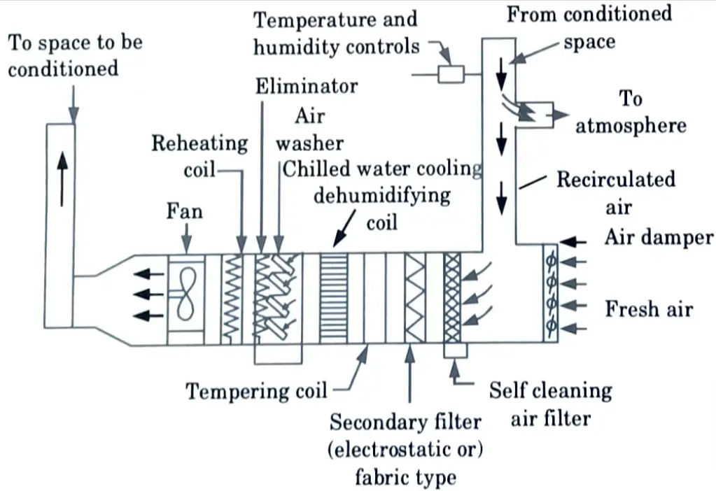
b. Explain different components of central air-conditioning system.
Ans. Central System :
- 1. This type of system is suitable for air-conditioning large space such as theatres, cinemas, restaurants, exhibition halls, or big factory spaces where no sub-division exists.
- 2. The central systems are generally employed for the loads above 25 tonnes of refrigeration and 2500 m3/min of conditioning air.
- 3. A central system that serves multiple rooms necessitates individual control of each room. The condenser, compressor, dampers, heating, cooling, and humidifying coils, as well as the fan, are all housed in the basement.
- 4. The conditioned air is delivered to the various rooms via supply ducts and returned to the control plant via return ducts. A portion of the supply air to the rooms could be exhausted outside.
- 5. Outdoor air enters through an intake located on the side of the building that is least exposed to solar heat. It should not be placed near the ground or on a dusty roof.
- 6. After passing through the damper, the air is filtered. The filters can be mechanically cleaned, replaceable-cell type, or electrostatic.
- 7. The cleaned air is then routed through the following equipment: temperature (or preheater) coil, cooling coil, humidifier (air washer), heating coils, and finally the fan.
Section 6 : Cooling Load in HVAC System
a. Explain the procedure to estimate the cooling load with the help of suitable example.
Ans. 1. Cooling load calculation is one the most challenging things in the HVAC industry.
2. There are a few methods suggested by ASHRAE (American Society of Heating, Refrigerating and Air-Conditioning Engineers) to calculate the cooling load.
3. Following example gives us the manual way to calculate the cooling load.
Example: Residential cooling load calculation suggested by ASHRAE. ASHRAE residential cooling load calculation can be broken into 5 parts for the following :
1. Windows Sensible Cooling Load Calculation: The sensible cooling load of windows is calculated by multiplying the area of the windows by the glass load factor (GLF). The formula used is :
q = Aw (GLF)
where,
q = Sensible cooling load, W
A = Area of window, m²
GLF = Glass load factor, W/m2
2. Doors Sensible Cooling Load Calculation: The sensible cooling load of doors is calculated by multiplying the area of the doors by the U-factor of the doors and the cooling load temperature difference (CLTD). The formula used is :
q = AdUd(CLTD)
where, Ad = Area of door, m²
Ud = Door U-factor, W/(m².K)
CLTD = Cooling load temperature difference, K
3. Walls Sensible Cooling Load Calculation: The sensible cooling load of walls is calculated by multiplying the area of the wall by the U-factor of the walls and the cooling load temperature difference (CLTD). The formula used is :
q = AwUw(CLTD)
where, Aw = Area of wall, m2
Uw = Door U-factor, W/(m².K)
4. Ceilings and Floors Sensible Cooling Load Calculation: The sensible cooling load of ceilings and floors is calculated by multiplying the area of the ceilings and floors by the U-factor of the ceilings and floors and the cooling load temperature difference (CLTD). The formula used for ceilings and floors is :
q = AcUc(CLTD) + AfUf(CLTD)
where, Ac = Area of ceiling, m²
Af = Area of floor, m²
Uc = Ceiling U-factor, W/(m².K)
Uf = Floor U-factor, W/(m².K)
5. Infiltration Sensible Cooling Load Calculation: The sensible cooling load of infiltration is calculated by multiplying 1.2 by the specific heat of air, the air change rate, room volume and the difference between designed indoor and outdoor temperature. The formula used for infiltration is :
q = 1.2(ACH)(V)(to – ti)(1000/3600)
where, ACH = Air change per hour, l/h
V = Volume of room, m3
to = Outdoor temperature, °C
ti = indoor temperature, °C
By adding all the above 5 parts we get the total sensible cooling load. Now to calculate the total cooling load, multiply the total sensible cooling load by the latent load factor.
b. A seminar hall for seating 250 persons is to be maintained at 22°C DBT and 50 % RH. The outside air conditions are 40 °C DBT and 27 °C WBT. The various loads in the auditorium are as follows :
Seasible and latent heal loads per person 80 W and 50 W respectively; Lights and fans, l5000 W; Sensible heat gain through glass, walls, ceiling etc., 12000 W; The air infiltration is 30 m³/min;
Determine room sensible heat factor.
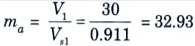
Ans. Given: Number of person = 250 Td2 = 22 °C, ɸ2 = 50 %, Td1 = 40 °C, Tur = 27 °C, QS = 80 W, QL = 50, QSL = 15 kW, QSG = 12 kW, V1 = 30 m³min.
1. Flow diagram for given air given air conditioning system is shown in Fig. 5.
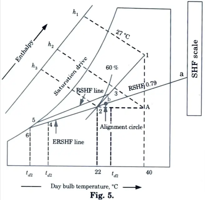
2. From psychrometric chart at point 1,
Specific volume, Vs1 = 0.911 m³kg of dry air
Enthalpy, h1 = 85 kJ/kg of dry air
3. At point 2 h2 = 45.5 kJ/kg of dry air
4. Locate point A by drawing horizontal and vertical lines through point 1 and 2.
Enthalpy of air at point A = 66 kJ/kg of dry air
5. Mass of infiltrated air at point 1,
6. Seasible heat gain due to infiltration air = ma (hA – h2)
= 32.93 (6645.5) = 675.065 kJ/min
7. Latent heat due to infiltration
ma(h1 – hA) = 32.93 (85 86)

8. Total sensible heat gain from persons
= QS per person x Number of person
= 80 x 250 = 20000 W = 20 kW
9. Total latent heat gain from persons = QL x number of person
= 50 x 250 = 12500 W = 12.5 kW
10. Total sensible heat gain
= Sansible heat gain due to infiltration + Sensible
heat gain from persons + QSL + QSG
= 11.25 + 20 + 15 + 12 = 58.25 kW
11. Total latent heat gain in room
= Latent heat gain due to infiltration + Latent heat gain from persons
= 10.42 kW + 12.5 kW = 22.92 kW

Section 7 : Curved Blade Vanes in HVAC System
a. Compare the characteristic of backward and forward curved blade vanes with the help of suitable sketches.
Ans. Sketches :
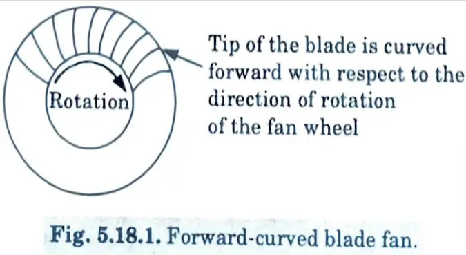
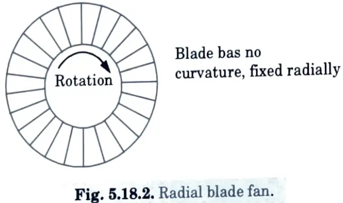
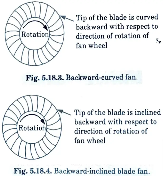
Comparison of Backward and Forward Curved Blade Vanes :
- 1. Backward curved blade vanes operate at a lower RPM and Power, henceforth, producing an efficiency that is higher than that of forward curved blade vanes.
- 2. Backward curved blade vanes have a smoother working as compared to forward curved blade vanes.
- 3. Backward curved blades centrifugal fan have 13.43 % higher efficiency on an average as compared to forward curved blades centrifugal fan.
- 4. Forward curved blades centrifugal fan utilise on an average 18.36 % more power as compared to backward curved blades centrifugal fan.
- 5. Forward curved blades centrifugal fan operate on an average 24.91 % more RPM as compared to backward curved blades centrifugal fan.
b. The main air supply duct of an air conditioning system is 800 mm x 600 mm in cross- section and carries 300 m³/min of standard air. It branches into two ducts of cross section 600 mm x 500 mm and 600 mm x 400 mm. If the mean velocity in the larger branch is 480 m/min, find :
1. Mean velocity in the main duct and the smaller branch, and
2. Mean velocity pressure in each duct.
Ans. Given: a1 = 800 mm = 0.8 m, b1 = 600 mm = 0.6 m, Q1 = 300 m3/min
=5 m3/s, a2 = 600 mm = 0.6 m, b2 = 500 mm = 0.5, a3 = 600 mm
= 0.6 m, b3 = 400 mm =0.4 m, V2 = 480 m/min = 8 m/s
1. The cross-section of the duct is shown in Fig. 7.
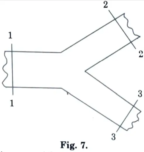
2. Cross-section area of the main duct,
A1 = a1b1 = 0.8 x 0.6 = 0.48 m²
Cross sectional area of the larger branch,
A2 = a2b2 = 0.6 x 0.5 – 0.3 m²
And cross-sectional area of the smaller branch,
A3 = a3b3 = 0.6 x 0.4 = 0.24 m2
3. We know that the velocity in the main duct,
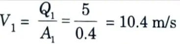
4. Quantity of air passing through the larger branch,
Q2 = A2V2 = 0.3 x 8= 2.4 m³/s
5. Quantity of air passing through the smaller branch,
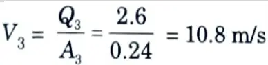
Q3 = Q1 – Q2= 5 – 2.4 = 2.6 m3/s
6. Mean velocity in the smaller branch,
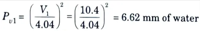
7. We know that velocity pressure in the main duct,
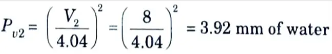
8. Mean velocity pressure in the larger branch,
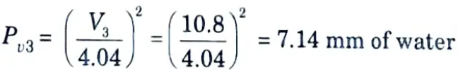
9. Mean velocity pressure in the smaller branch,
1 thought on “HVAC Systems: AKTU Question Paper with Easy Solutions”